1–Introduction
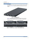
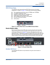
iSR6200 Router Chassis
ISR651101-00 J 1-3
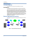
This configuration has the following additional requirements:
At least one Fibre Channel port of iSR6200 connected to Fibre Channel
SAN.
Accessibility between the GbE ports on the router, port IP addresses of the
remote router, and GbE port IP addresses of the local routers.
Accessibility between the remote iSR6200 management port IP address and
local iSR6200 management port IP address.
When connecting SANs over long distances, you must determine the round-trip
latencies between two router connections. You can discover these round-trip
latencies using the ping command in the CLI. (See the iSR6200 Command Line
Interface (CLI) User’s Guide.)
Using this round-trip latency number, you can determine the window scaling factor
for GbE port, as described in “Performance Tuning” on page 2-4. By default,
window scaling is set to 1 (64K) TCP window size.
To map remote Fibre Channel devices to a local SAN:
1. If the remote router is not already associated with a local router, associate
the two routers with each other using one of these user interfaces:
The Add Remote Router wizard (see the iSR6200 Router Manager
User’s Guide).
The CLI command remotepeer add (see the iSR6200 Command
Line Interface (CLI) User’s Guide).
2. Create the initiator to target mapping using one of these methods:
The Map Remote Initiator/Target wizard (see the iSR6200 Router
Manager User’s Guide).
The CLI remotemap add command (see the iSR6200 Command
Line Interface (CLI) User’s Guide).
iSR6200 Router Chassis
The iSR6200 router chassis includes the following hardware components:
Full-wide, 1U, rack mount
Two bays for hot-replaceable ISR blades
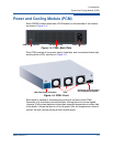
Two bays for hot-replaceable PCMs
One mid-plane with two × EEPROMs
Dual 275-watt power supplies


