


APPLICATION
2.4 Serial I/O
2-47
4513/4514 Group User’s Manual
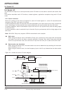
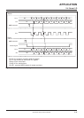
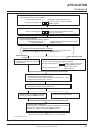
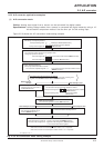
Fig. 2.4.6 Slave serial I/O example
b3 b0
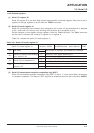
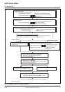
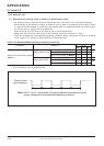
➀ Disable Interrupts
Serial I/O interrupt is temporarily disabled.
Interrupt enable flag INTE
Interrupt control register V2
“0”
✕✕
All interrupts disabled (DI instruction)
Serial I/O interrupt occurrence disabled
(TV2A instruction)
0
✕
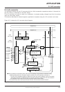
➁ Set Serial I/O
Serial I/O mode register J1
b3 b0
✕
1
✕
Exernal clock selected (TJ1A instruction)
Serial I/O port selected
0
g0 h
➂ Clear Interrupt Request
Serial I/O interrupt activated condition is cleared.
Serial I/O transmit/receive
completion flag SIOF
“0”
Serial I/O interrupt activated condition cleared
(SNZSI instruction)
Note when the interrupt request is cleared
When ➂ is executed, considering the skip of the next instruction according to the
SIOF flag, insert the NOP instruction after the SNZSI instruction.
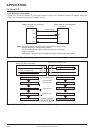
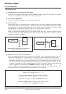
When interrupt is
not used
When interrupt is used
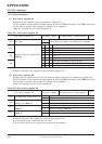
➃ Set Interrupt
Interrupts except serial I/O is enabled
(EI instruction)
➃ Set Interrupt
Serial I/O interrupt temporarily disabled is enabled.
b3 b0
1
✕✕✕
Interrupt control register V2
Serial I/O interrupt occurrence
enabled (TV2A instruction)
Interrupt enable flag INTE
“1”
All interrupts enabled
(EI instruction)
➄ Set When Transmit/Receive Operation Start Enabled
Serial transfer start state (SST instruction)
System enters to control signal transmission enabled state (“L” level)
However, S
CK
pin initial level = “H” level
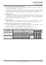
➅ Start Serial I/O Operation
Serial transfer starts by clock of master side
➆ Check Serial I/O Interrupt Request
SIOF flag is checked (SNZSI instruction).
➆ Serial I/O Interrupt Occur
➇ Receive Data Processing
System enters to control signal transmission disabled state (“H” level)
Data processing received by serial transfer is executed.
Register SI → register A, register B (TABSI instruction)
When serial communication is executed, ➄ to ➇ are repeated.
“✕”: it can be “0” or “1.”