4513/4514 Group User’s Manual
HARDWARE
1-47
FUNCTION BLOCK OPERATIONS
VOLTAGE COMPARATOR
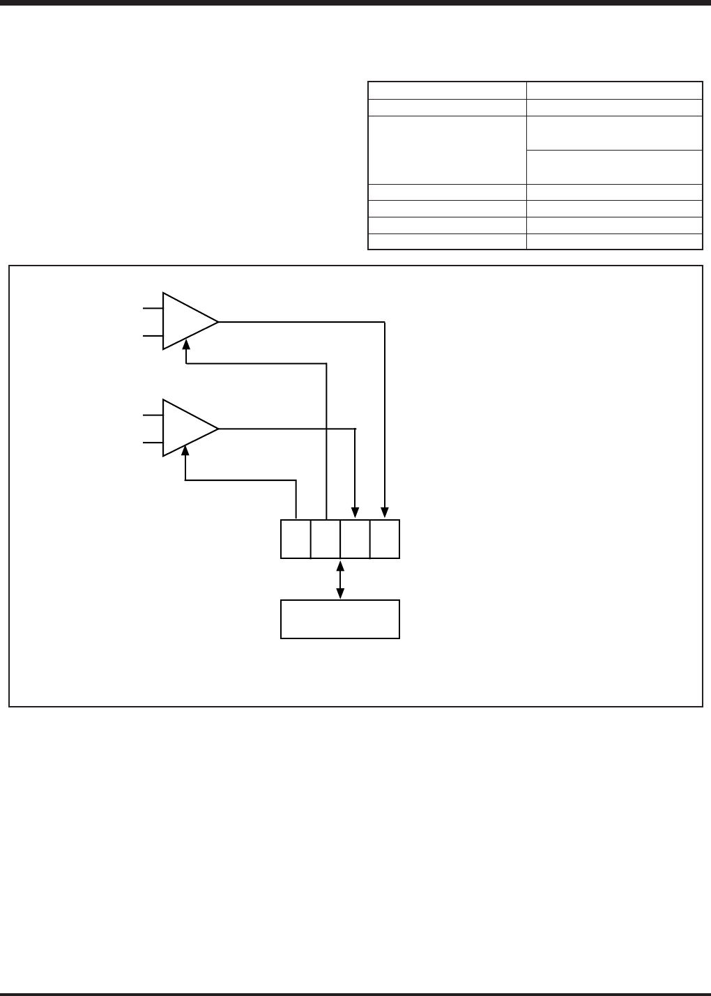
The 4513/4514 Group has 2 voltage comparator circuits that
perform comparison of voltage between 2 pins. Table 17 shows
the characteristics of this voltage comparison.
Table 17 Voltage comparator characteristics
Characteristics
2 circuits (CMP0, CMP1)
CMP0-, CMP0+
(also used as AIN0, AIN1)
CMP1-, CMP1+
(also used as AIN2, AIN3)
3.0 V to 5.5 V
0.3 VDD to 0.7 VDD
Typ. 20 mV, Max.100 mV
Max. 20
µ
s
Parameter
Voltage comparator function
Input pin
Supply voltage
Input voltage
Comparison check error
Response time
Fig. 31 Voltage comparator structure
CMP0–/A
IN0
CMP0+/A
IN1
–
CMP0
+
CMP1–/A
IN2
CMP1+/A
IN3
–
CMP1
+
Q3
3
Q3
2
Q3
1
Q3
0
Register A (4)
TQ3A
TAQ3
Voltage comparator control register Q3 (4)
Note: Bits 0 and 1 of register Q3 can be only read.


