APPLICATION
2-58
4513/4514 Group User’s Manual
2.8 Voltage drop detection circuit
2.8 Voltage drop detection circuit
The built-in voltage drop detection circuit is designed to detect a drop in voltage and to reset the microcomputer
if the supply voltage drops below a set value.
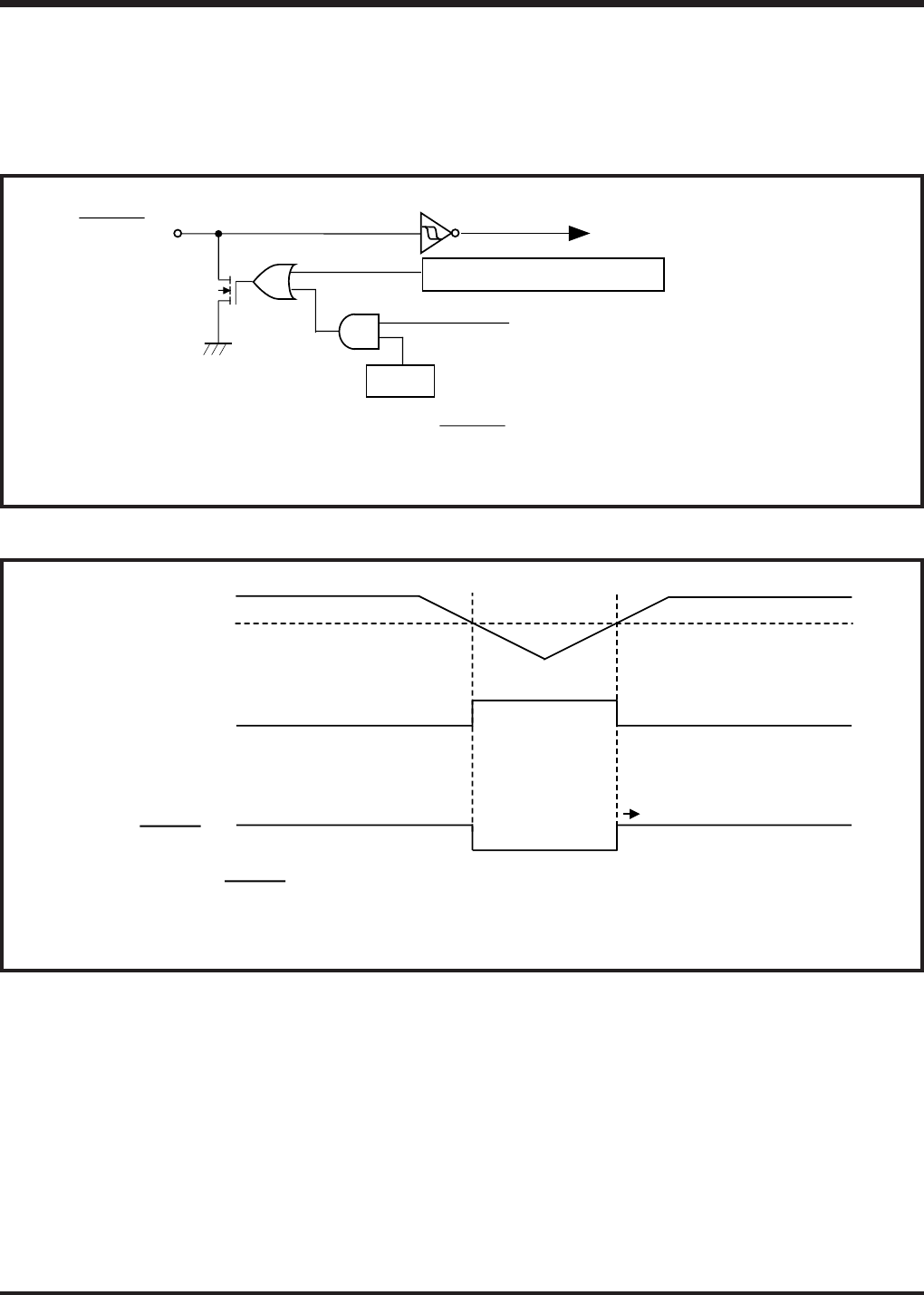
Figure 2.8.1 shows the voltage drop detection reset circuit, and Figure 2.8.2 shows the operation waveform
example of the voltage drop detection circuit.
Fig. 2.8.1 Voltage drop detection reset circuit
Fig. 2.8.2 Voltage drop detection circuit operation waveform
Note: Refer to section “3.1 Electrical characteristics” for the reset voltage of the voltage drop detection
circuit.
Voltage drop detection circuit
Internal reset signal
RESET pin
Watchdog timer output
WEF
Note: The output structure of RESET pin is N-channel open-drain.
VDD
VRST (detection voltage)
Voltage drop detection
circuit output
The microcomputer starts
operation after f(XIN) is counted
16892 to 16895 times.
RESET pin
Notes 1: Pull-up RESET pin externally.
2: Refer to the voltage drop detection circuit in the electrical characteristics
for the rating value of VRST (detection voltage).


