


Riverstone Networks RS Switch Router User Guide Release 8.0 8-9
ATM Configuration Guide Traffic Management
Relative Latency
When you use the
atm set vcl-qos
command to define a VC’s QoS policy, you can set a value for relative latency
by specifying the
relative-latency
parameter. Increasing relative latency can increase the accuracy of the
achieved rates. This is because each queue has a quota of bytes to transmit, and the packets that are sent may not exactly
equal that quota. Therefore there is going to be either excess bytes sent, or a shortage of bytes sent. When a packet to
transmit exceeds the quota, an implementation could choose to send the packet and go over the quota, or not send it
and go under the quota. This feature allows an excess number to be sent, so up to 1499 extra bytes can be sent during
a period. This is a significant number when the byte count for a queue is around 1500; however, its affect decreases as
the byte count increases.
Increasing the relative latency also increases the amount of time that a queue waits to transmit a packet after it has used
up its quota. For example, if a queue with weight 10 used up its quota before the other queues had transmitted, it would
potentially have to wait for the other 90 percent of the total byte count to be sent before it could send again. The time
is dependent upon the VC's rate.
For configurations in which a latency sensitive application has a low percentage of a slow link speed, it is best to put
that application on the control queue and use "WFQ with strict priority." Optionally, you can set the relative latency to
1, as long as the achieved rates are accurate.
Additionally, when increasing relative latency values, you should also consider increasing the size of the buffers. This
is because packets may be held off for longer times.
Decreasing relative latency has the effect of:
•
Decreasing worst case latency seen by a bursty flow.
•
Decreasing buffer requirements for the VC.
•
Possibly decreasing the achievable accuracy of the selected weights.
Controlling Buffers for Each VC
When VCs queue data, they consume memory resources on the ATM card. By default, the hardware limits the number
of internal buffers that each VC can use (21 * 240 bytes) for each queue. Generally, you should not have to set the
number of internal buffers. However, if a bursty application is suffering loss (i.e., jumpy video), then you can increase
the buffers for that queue by using the
atm set vcl-buffering
command. The best way to determine the correct
setting is to use a network analyzer to find the maximum burst, or to determine the correct settings through
experimentation.
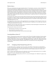
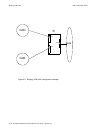
8.4.2 Configuring Virtual Channel Groups (OC-12)
A virtual channel group is a grouping of up to four separate virtual channels. This grouping of virtual channels is
treated as one large virtual circuit. This is due to the fact that the VC group is seen as one virtual interface by the IP
layer. For example, OSPF will see a point-to-point connection instead of multiple connections for all the virtual
channels within the VC group.
Each VC within a virtual channel group can be assigned one (or more) of four internal priority levels: low, medium,
high, and control. These internal priority levels apply to IP packets.
In addition to assigning an internal priority level for a VC, you can also designate a VC within the VC group to carry
broadcast/multicast traffic.