


Riverstone Networks RS Switch Router User Guide Release 8.0 5-27
Bridging Configuration Guide Tunneling VLAN packets across MANs
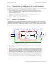
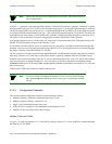
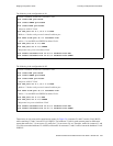
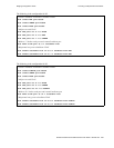
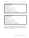
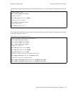
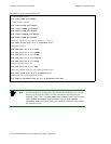
The following is the configuration for R1:
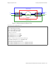
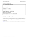
The following is the configuration for R2:
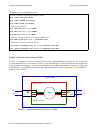
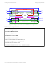
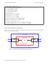
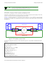
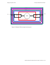
The following is an example where a customer VLAN has multiple tunnel entry or exit ports spread across routers.
Figure 5-8 shows customers C1 and C2 sharing the VLAN BLUE. Traffic for customer C1 can arrive on tunnel entry
ports on routers R1, R2, or R3. Broadcast or multicast traffic arriving on et.2.1 on R1 is tunneled on backbone VLAN
RED and will be seen by C1 users on R2 and R3. C2 users on R4 will not see the C1 traffic since the tunnel backbone
port on R4 belongs to the backbone VLAN PURPLE.
! Create backbone VLAN and customer VLAN
vlan create RED port-based
vlan create BLUE port-based
! Add ports to VLANs
vlan add ports et.2.1, et.3.1 to BLUE
vlan add ports et.4.1 to RED
! Make et.4.1 both a trunk port and a tunnel backbone port
vlan make trunk-port et.4.1 stackable-vlan
! Map tunnel entry ports to backbone VLAN
vlan enable stackable-vlan on et.2.1 backbone-vlan RED
vlan enable stackable-vlan on et.3.1 backbone-vlan RED
! Create backbone VLAN and customer VLAN
vlan create RED port-based
vlan create BLUE port-based
! Add ports to VLANs
vlan add ports et.6.1, et.7.1 to BLUE
vlan add ports et.5.1 to RED
! Make et.5.1 both a trunk port and a tunnel backbone port
vlan make trunk-port et.5.1 stackable-vlan
! Map tunnel exit ports to backbone VLAN
vlan enable stackable-vlan on et.6.1 backbone-vlan RED
vlan enable stackable-vlan on et.7.1 backbone-vlan RED