


Riverstone Networks RS Switch Router User Guide Release 8.0 5-17
Bridging Configuration Guide GARP/GVRP
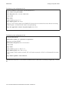
5.11.3 Configuration Example
Consider the following configuration example.
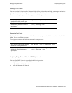
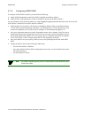
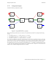
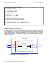
Figure 5-2 Using GARP/GVRP on a network
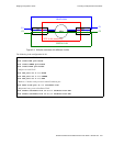
Routers R4 and R5 pass traffic between two networks. The administrator used the CLI to configure the following
VLANs:
•
VLAN RED on ports et.1.1- 1.3 on R1, and on et.4.1 - 4.3 on R6.
•
VLAN GREEN on ports et.2.1- 2.3 on R2, and on et.5.1 - 5.3 on R7.
•
VLAN BLUE on ports et.3.1- 3.3 on R3, and on et.6.1 - 6.3 on R8.
No VLANs were configured on R4 and R5. Instead, dynamic VLAN creation was enabled. So when any of the edge
routers (R1, R2, R3, R6, R7, or R8) send a request for a VLAN to the core routers (R4 and R5), and the VLAN does
not exist on the core routers, that VLAN is dynamically created on the port of the router that received the request.
For example, R4 receives a receives a request for VLAN RED on port 7.1. VLAN RED is created dynamically on port
7.1 of R4. This is then propagated across the bridged LAN to all the other routers. If dynamic VLAN creation was not
enabled on R4, it would have dropped the traffic for VLAN RED.
R1
et.1.2
et.1.3
.
R2
et.2.1
R3
st.1
et.4.2
et.4.3
R6
et.4.1
8.1
et.5.1
R7
et.6.1
R8
R5
et.2.2
et.2.3
et.3.1et.3.2
et.3.3
et.5.2
et.5.3
et.6.2
et.6.3
et.1.1
8.3
8.2
st.1
7.1
R4
7.3
7.2