MZ3500
3-2.
Main
CPU and I/O
port
M
A
I
N
C
P
u
r^
IX
A2
A3
A4
—££-1
A6
A
v~\
r
M
P
C
IORQ
M
i
j^
Y 1
iZ
(jtA.
Y3
Y4
G2
B
Y5
Ol Y6
74LSI38
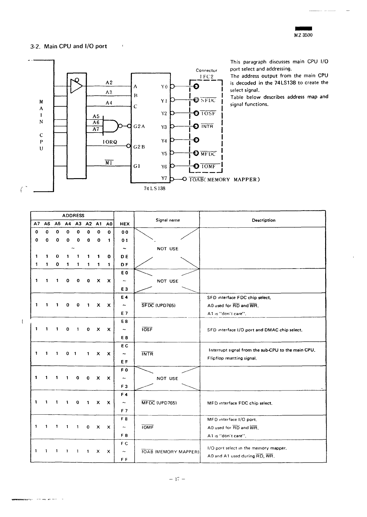
This
paragraph
discusses
main
CPU I/O
Connector
Port
select
and
addressing.
I
PC
2 The
address
output
from
the
main
CPU
|~^T
1 is
decoded
in the
74LS138
to
create
the
""
v
select
signal.
~s
f^-r-^r-.
—
r
Table
below
describes
address
map and
~~>
\J>
-•>
r DL
signal
functions.
J
\J I
Obr
-)
f\
J -\J
^
0
MFUC
•
\J
lUMr
5 O
IOABCMEMORY
MAPPER)
ADDRESS
A7 A6 A5 A4 A3 A2 A1 AO
00000000
00000001
11011110
11011111
^^^Qooxx
^^^QO•^xx
iiiotoxx
11101
1 X. X
1111QOXX
1 1 1 1 0 1 X X
1 1 1 1 1 0 X X
1
1 1 1 1 1 X X
HEX
00
01
DE
DF
EO
E3
E4
E
7
E8
EB
EC
EF
FO
F3
F4
F
7
F8
F
B
FC
F
F
NOT USE
NOT USE
SFDC
(UPD765)
IOSF
INTR
NOT USE
MFDC (UPD765)
IOMF
IOAB
(MEMORY
MAPPER)
SFD
interface
FDC
chip
select.
AO
used
for RD and WR.
A1 is
"don't
care".
SFD
interface
I/O
port
and
DMAC chip select.
Interrupt
signal
from
the
sub-CPU
to the
main
CPU.
Flipflop
resetting signal.
MFD
interface
FDC
chip
select.
MFD
interface
I/O
port.
AO
used
for RD and WR.
AT
is
"don't
care".
I/O
port
select
in the
memory mapper.
AO
and A1
used
during
~W5.
WR.


