


M
7
3500
8 4
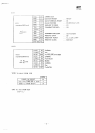
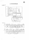
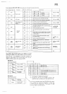
System
SW1
(DIP
SW)
(User
operative
through
the
cabinet
bottom)
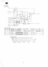
No
1
2
3
4
5
6
7
8
9
10
Signal
name
SW1
SW2
SW3
SW4
SW5
SW6
SW7
FD1
(SW8)
P/M
(SW9)
Function
Printer
select
CRT
select
Choice
of
decimal
point output
format
RS232C
assign
Key
shift mode
setup
Choice
of CG
for
display
Position
ON
OFF
ON
OFF
ON
OFF
ON
OFF
ON
OFF
ON
OFF
ON
OFF
ON
OFF
ON
OFF
Polarity
L
H
L
H
L
H
L
H
L
H
L
H
L
H
L
H
L
H
Description
SW2 SW1
ON ON
CE332P
OFF
ON
MZ1P02
ON OFF
IO2824
OFF
OFF
High
resolution
CRT
(MZ1D02. MZ1D03)
Medium
resolution
CRT
(MZ1D01, MZ1D06)
A
period
is
output
for a
decimal point
A
comma
is
outputted
for a
decimal point
Low
state
or
open
ER
signal
during data output
will
result
in an
error
The
signal
ER
becomes
invalid
CD is
high
as
long
as
power
is on to the
main
unit
CD
goes
high only during
data
output
However,
it
would
not go
high
if the
echo
back
function
is
on the
host
side
An
error
is
cause
when
the PO
signal
is
high
during
data
output
Polarity
is
inverted
for the
above
Normally
in
capital
letter,
but in
small letter
when
shifted
Normally
small
leter
and in
capital letter when
shifted
3500
CG
will
be
assigned
when
the 200
raster
CRT is in use
2000
CG
will
be
assigned
when
the 200
raster
CRT is in use
^=—
=T
#47 pin of MMR
£48 pin of MMR
#51 pin of MMR
#52
pin of MMR
ToCTS,
DSR
of
the
8251
ToCTS
of the
8251
#54
pin of MMR
(FDD
P/M
signal
(To A3 CG)
NC
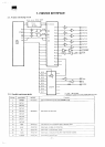
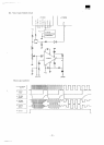
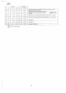
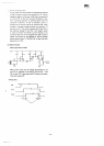
Dip
switches
(A) and (B)
located
on the PWB are
used
for
servicing
the MFD or for
other
machine
service
and
there
fore
the
user
is not
supposed
to use
these
switches
In
addition,
these
switch
must
be
used
when
either
the CE
330M
or
331M
is
used
as the
expansion
MFD
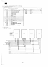
DIPSW(A)
No
1
2
3
4
Signal name
SEC
(SW1A)
FD2
(SW2A)
FD3
(SW3A)
SRQ
(SW4A)
44 pin of MMR
56
pin of MMR
58
pin of MMR
Bus
request
to
sub-CPU
DIPSW
(B)
No
1
2
Signal
name
SRES
(SW1B)
SW2B
SUB CPU
reset
signal
SUB CPU BUS
select
signal
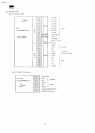
t
1
OFF
ON
OFF
ON
OFF
ON
OFF
ON
2
OFF
OFF
ON
ON
OFF
OFF
ON
ON
3
OFF
OFF
OFF
OFF
ON
ON
ON
ON
WhenSH
in use
When
DH in use
—
—
Use
of the
CE330M
as an
expansion
unit
Use
of the
CE331M
as an
expansion
unit
Check
mode
*1
Check
mode
*2
*1
Test
program
is
loaded
and
executed
\
*2
Provided
for the
test
of the MFD
interface
The
read/write
test
is
carried
out for the
expansion
unit
Used
for an
individual
test
of the CPU PWB
When these
three switches
are
turned
off
altogether,
it
makes
the
sub
CPU
operated
independently
To be
used
in th ON
condition
under
a
normal
situation