


MZ3500
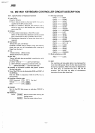
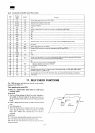
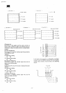
10-5. keyboard
controller
signal description
PIN
No
1
2
3
4
5
6
7
8
9
10
11
12
19
20
21
22
23
24
25
26
27
30
31
32
34
35
36
38
39
40
Porality
signal
name
TO
XTAL1
XTAL2
RESET
SS
INT
EA
RD
PSEN
WR
ALE
DBO
DB7
GND
P20
P21
P22
P23
PROG
VDO
P10
P13
P14
P15
P17
P24
P25
P27
T1
Vcc
IN/OUT
IN
IN
IN
IN
IN
IN
IN
-
-
-
-
IN
IN
OUT
OUT
IN
-
IN
OUT
-
OUT
IN
IN
IN
IN
Function
Output
data signal
from
the sub CPU
(D(O)
Internal clock oscillator
crystal
input
Internal
clock oscillator crystal
input
Processor
initialize
+
5V
Strove
of
D(C) that also
is
used
for
interrupt
to the
keyboard
side
(ST(O)
GND
NC
NC
NC
NC
RETURN
signal
from
the
keyboard
is
input
when
a key is
pushed
during
key
search
0V
supply
Output
data
signal
from
key
(D(K))
Strobe
of
D(K)
which
also
is
used
for
interrupt
to the CPU
side
(ST(K))
Not
used
NC
+
5V
Strobe
to the
keyboard
unit
by
which
a
hexadecimal
code
is
sent
out for
generation
shift
pulses
to
terminals XOX15ofthe4515
decorder
during
key
search
NC
Pins
used
to
activate
the
keytop
embeded
LED
#32 pin
Alphabets
and
symbols
(LOCK)
#33 and #34 are not
used
Not
used
Keyboard
type
identifier
pin
Keyboard
type
is
identified
by
mears
of
KSO, KS1,
KS2 of
KUC1
an
KUS2.
whether
it is GND or NC
Acknowledge
input
from
the CPU
(ACK(O)
Sent
only
when
the CPU
receives
a
correct
data
+
5V
supply
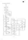
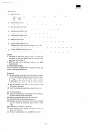
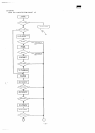
11.
SELF
CHECK
FUNCTIONS
The
-3500
performs self-check test during
initial
program
loading
of the
ROM. 11-1.
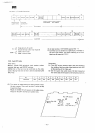
Test
regarding
the
main
CPU
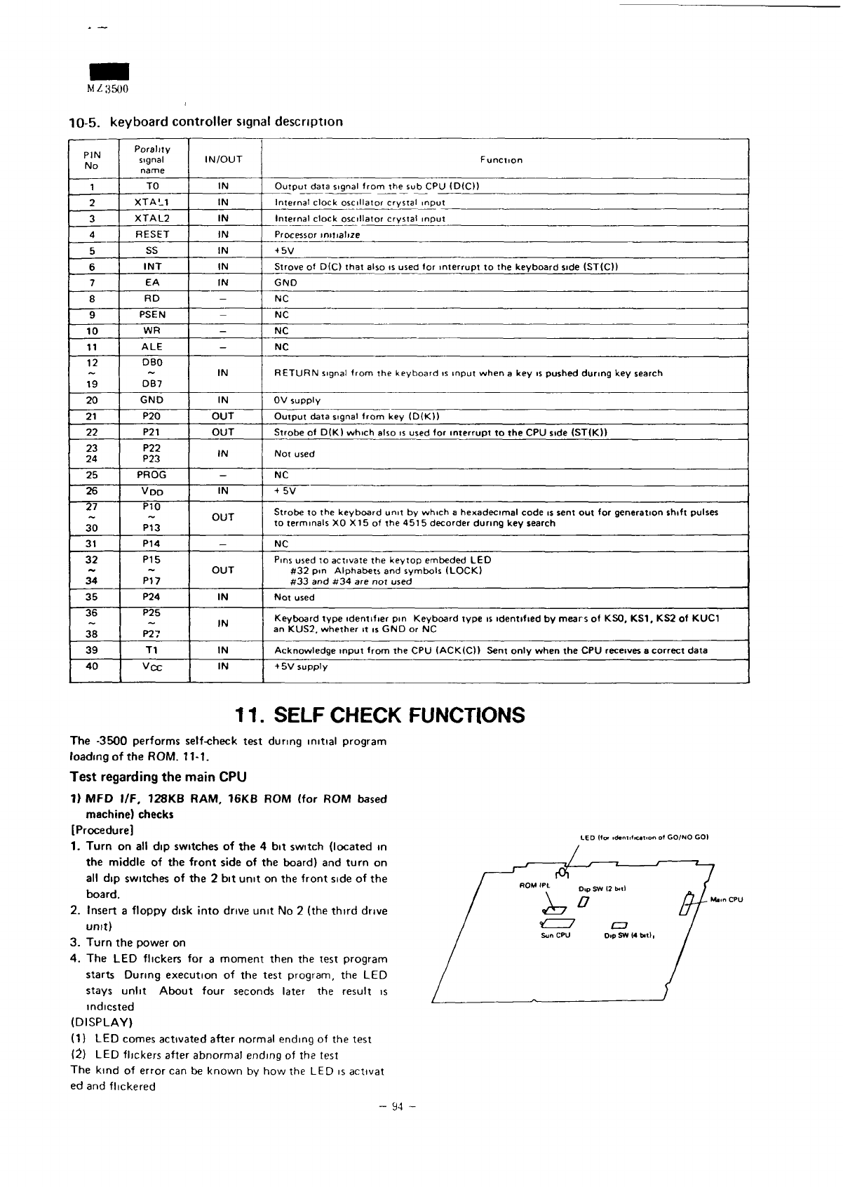
1) MFD
I/F.
128KB
RAM. 16KB
ROM
(for
ROM
based
machine)
checks
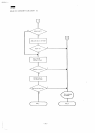
[Procedure]
1.
Turn
on all dip
switches
of the 4 bit
switch (located
in
the
middle
of the
front
side
of the
board)
and
turn
on
all
dip
switches
of the 2 bit
unit
on the
front
side
of the
board.
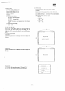
2.
Insert
a
floppy
disk
into
drive
unit
No 2
(the
third
drive
unit)
3.
Turn
the
power
on
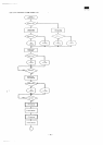
4. The LED
flickers
for a
moment then
the
test
program
starts
During
execution
of the
test program,
the LED
stays
unlit
About
four
seconds
later
the
result
is
mdicsted
(DISPLAY)
(1) LED
comes
activated after normal ending
of the
test
(2)
LED
flickers after
abnormal
ending
of the
test
The
kind
of
error
can be
known
by how the LED is
activat
ed and
flickered
LED
(fof id«niific«Tion
of
GO/NO
GO)