


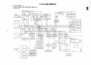
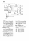
MZ3500
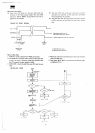
2)
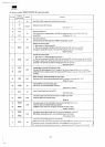
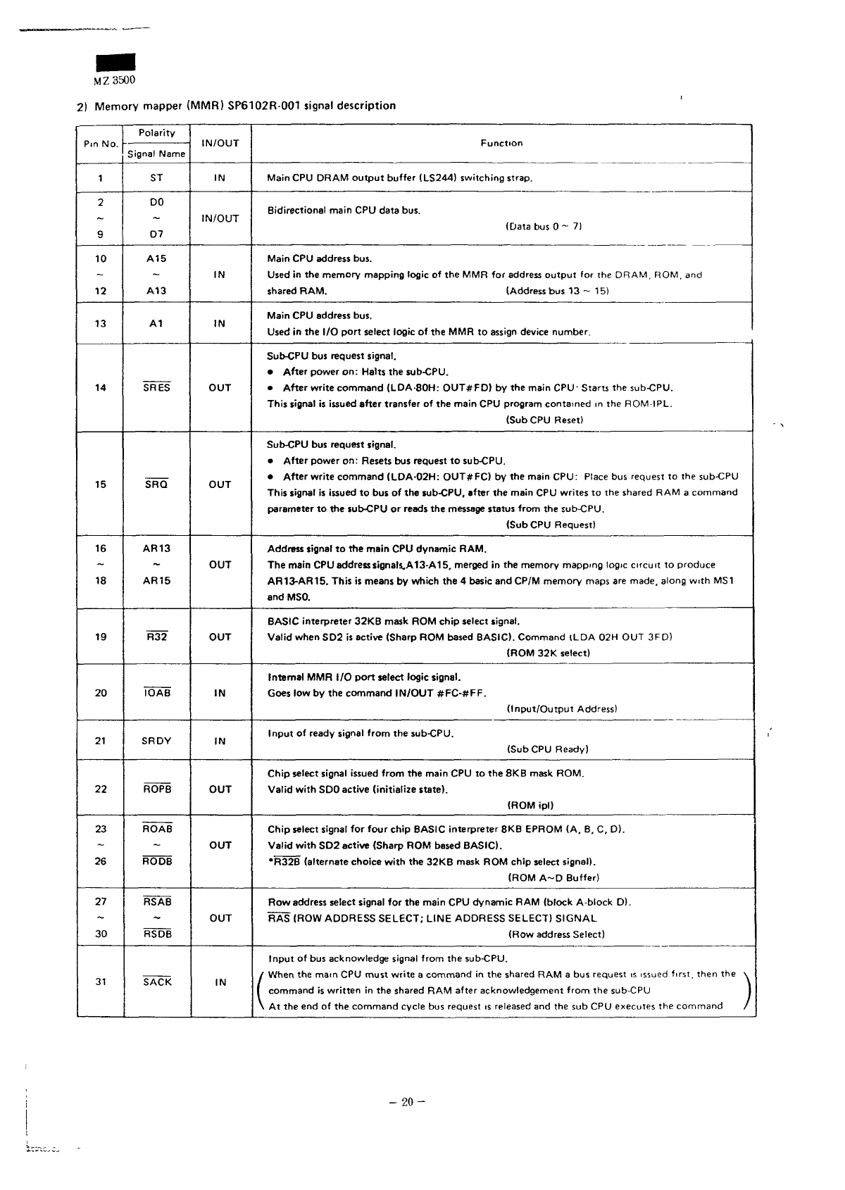
Memory
mapper
(MMR)
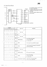
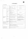
SP6102R-001
signal
description
1
2
9
10
12
13
14
15
16
18
19
20
21
22
23
26
27
~
30
31
Polarity
Signal
Name
ST
DO
D7
A15
A13
A1
SRES
SRQ
AR13
AR15
R32
IOAB
SRDY
ROPB
ROAB
RODS
RSAB
~
RSDB
SACK
IN
IN/OUT
IN
IN
OUT
OUT
OUT
OUT
IN
IN
OUT
OUT
OUT
IN
Main
CPU
DRAM
output
buffer
(LS244)
switching
strap.
Bidirectional main
CPU
data
bus.
(Data
bus 0 ~ 7)
Main
CPU
address
bus.
Used
in the
memory mapping logic
of the MMR for
address
output
for the
DRAM,
ROM,
and
shared
RAM. (Address
bus 13 ~ 15)
Main
CPU
address
bus.
Used
in the I/O
port
select
logic
of the MMR to
assign
device
number.
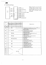
Sub-CPU
bus
request
signal.
•
After power
on:
Halts
the
sub-CPU.
•
After write command (LDA-80H: OUT#FD)
by the
main
CPU-
Starts
the
sub-CPU.
This
signal
is
issued after transfer
of the
main
CPU
program contained
in the
ROM-IPL.
(Sub
CPU
Reset)
Sub-CPU
bus
request
signal.
•
After power
on:
Resets
bus
request
to
sub-CPU.
•
After write command (LDA-02H
1
OUT#FC)
by the
main CPU'
Place
bus
request
to the
sub-CPU
This signal
is
issued
to bus of the
sub-CPU, after
the
main
CPU
writes
to the
shared
RAM a
command
parameter
to the
sub-CPU
or
reads
the
message
status
from
the
sub-CPU.
(Sub
CPU
Request)
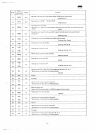
Address
signal
to the
main
CPU
dynamic RAM.
The
main
CPU
address
signals,
A
13-A
15,
merged
in the
memory mapping logic circuit
to
produce
AR13-AR15. This
is
means
by
which
the 4
basic
and
CP/M memory
maps
are
made,
along
with
MS1
and
MSO.
BASIC
interpreter 32KB
mask
ROM
chip
select
signal.
Valid
when
SD2 is
active (Sharp
ROM
based
BASIC). Command (LDA
02H OUT
3FD)
(ROM
32K
select)
Internal
MMR I/O
port
select
logic
signal.
Goes
low by the
command
IN/OUT
#FC-#FF.
(Input/Output
Address)
Input
of
ready
signal from
the
sub-CPU.
(Sub
CPU
Ready)
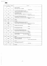
Chip select signal
issued
from
the
main
CPU to the 8KB
mask
ROM.
Valid
with
SDO
active
(initialize
state).
(ROM
ipl)
Chip select
signal
for
four
chip
BASIC interpreter
8KB
EPROM
(A. B. C, D).
Valid
with
SD2
active (Sharp
ROM
based
BASIC).
"R32B (alternate choice
with
the
32KB
mask
ROM
chip select signal).
(ROM
A~D
Buffer)
Row
address
select
signal
for the
main
CPU
dynamic
RAM
(block A-block
D).
RAS
(ROW
ADDRESS
SELECT; LINE
ADDRESS
SELECT)
SIGNAL
(Row
address
Select)
Input
of bus
acknowledge
signal
from
the
sub-CPU.
command
is
written
in the
shared
RAM
after
acknowledgement
from
the
sub-CPU
1
At the end of the
command
cycle
bus
request
is
released
and the sub CPU
executes
the
command
/
-
20-