


MZ3500
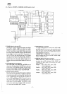
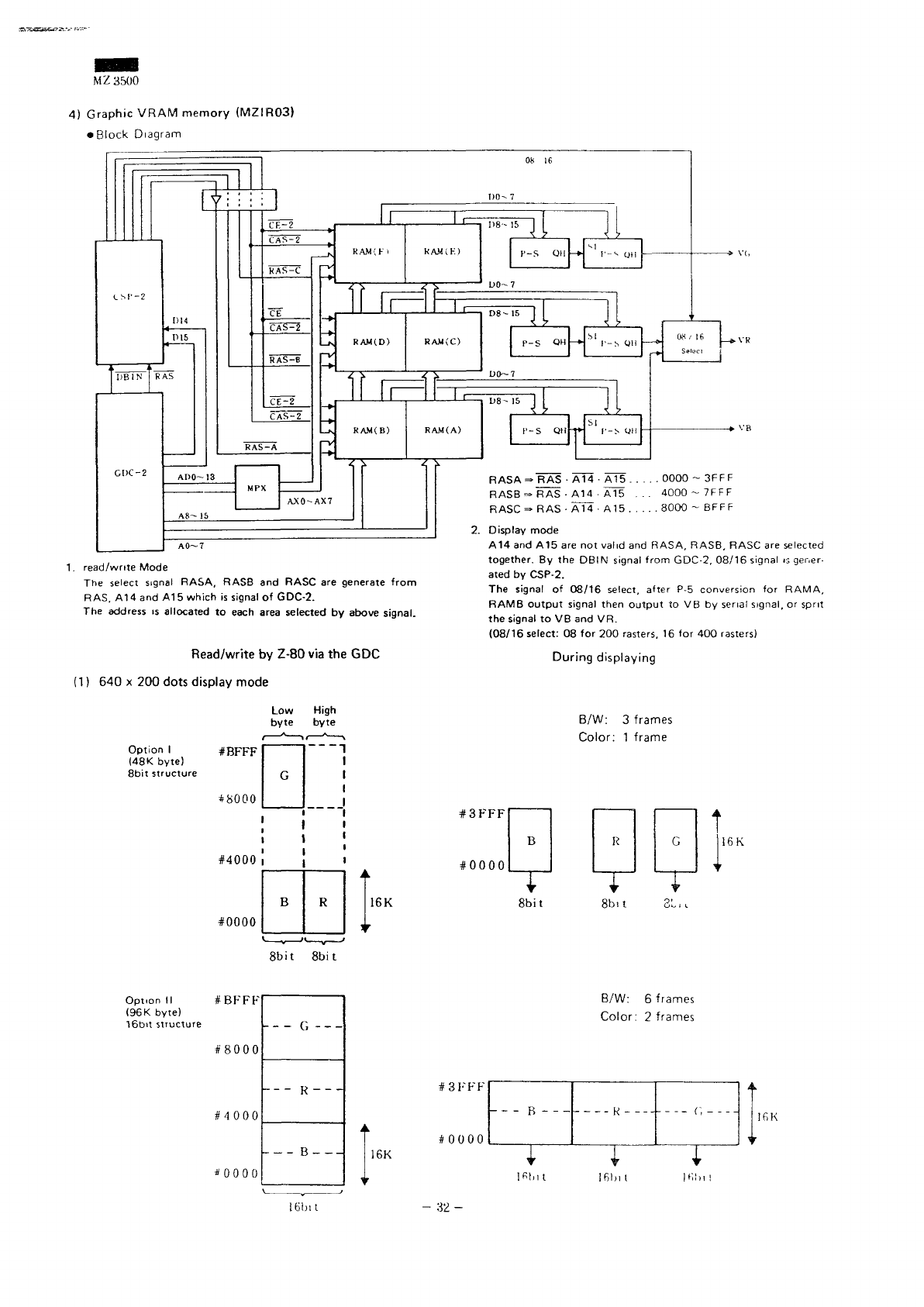
4)
Graphic
VRAM
memory
(MZIR03)
•
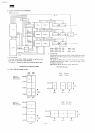
Block
Diagram
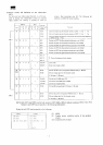
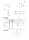
1.
read/write Mode
The
select signal
RASA, RASB
and
RASC
are
generate
from
RAS,
A14 and A1 5
which
is
signal
of
GDC-2.
The
address
is
allocated
to
each area selected
by
above
signal.
Read/write
by
Z-80
via the GDC
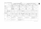
(1)
640 x 200
dots display mode
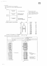
Option
I
#BFFF
(48K byte)
8bit
structure
+
8000
#4000
#0000
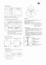
Low
byte
G
B
High
byte
1
A
R
i
R
ASA ^ RAS • A14 • A15
0000
~
3FFF
RASB~
RAS • A14 • AlS ...
4000-7FFF
RASC
=• RAS • A14 • A15
8000
~
BFFF
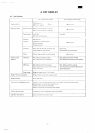
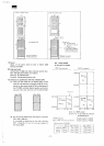
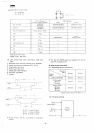
2.
Display
mode
A14 and A15 are not
valid
and
RASA, RASB, RASC
are
selected
together.
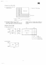
By the
DBIN
signal
from
GDC-2. 08/16 signal
is
gener-
ated
by
CSP-2.
The
signal
of
08/16 select,
after
P-5
conversion
for
RAMA,
RAMB
output
signal then
output
to VB by
serial
signal,
or
sprit
the
signal
to VB and VR.
(08/16
select:
08 for 200
rasters.
16 for 400
rasters)
During
displaying
B/W:
3
frames
Color:
1
frame
#3FFF
#0000
16K
16K
8bit
8bit 31,L
8bit
8bit
Option
II
#BFFF
(96K
byte)
16bit
structure
#8000
#4000
*0000
16K
#3FFF
#0000
B/W:
6
frames
Color:
2
frames
I
1
1
16K
ifit.it
16bit
-
32-