


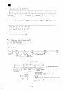
MZ350C
P,n
No
32. 31
23
22
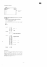
Signal
name
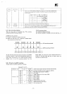
PSO.
1
RDATA
WINDOW
I/O
O
1
'
Function
Signal
used
to
obtain
tir
the
table
be
to
either
advance
or
delay
the
write
data
in
writi
rung
adjustment
for
reading.
The
WDATA
signal
ow
PSO
0
0
1
1
PS1
0
1
0
1
FM
Not
changed
-
-
-
MFM
Not
changed
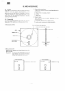
LATE
225~250ns
EARLY
225~250ns
-
ng
under
the MFM
mode,
is
controlled
as
shown
in
Read
data
from
the
drive
unit
consists
of
clock
bits
and
data
bits.
Signal
created
in the VFO
circuit
which
is
used
to
sample
RDATA.
Phase
syncroni^i
carried
out in the FDC for
RDATA
data
bits
and
WINDOW.
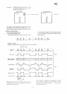
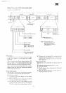
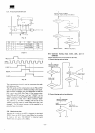
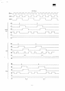
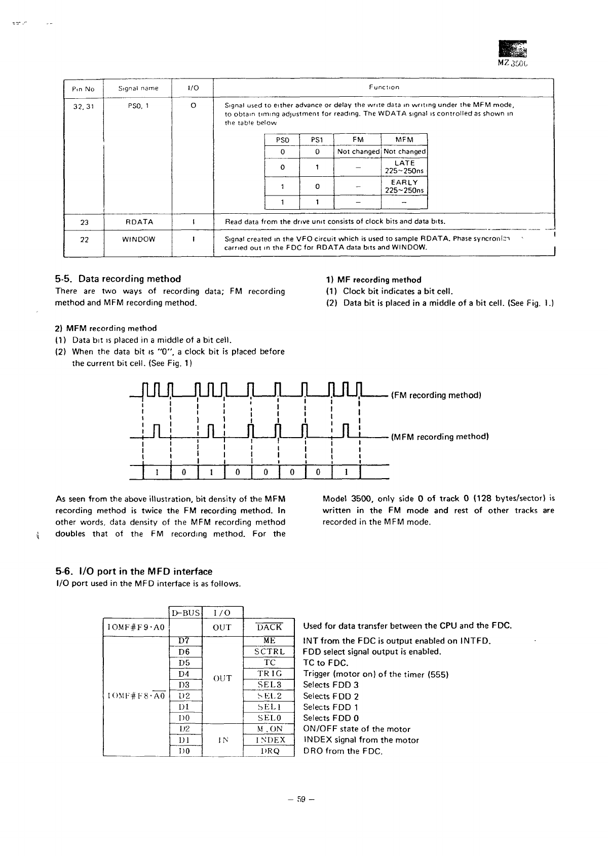
5-5. Data recording
method
There
are two
ways
of
recording data;
FM
recording
method
and MFM
recording
method.
1)
MF
recording
method
(1)
Clock
bit
indicates
a bit
cell.
(2)
Data
bit is
placed
in a
middle
of a bit
cell. (See Fig.
I.
2)
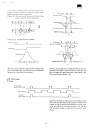
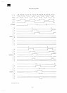
MFM
recording method
(1)
Data
bit is
placed
in a
middle
of a bit
cell.
(2)
When
the
data
bit is
"0",
a
clock
bit is
placed before
the
current
bit
cell. (See Fig.
1)
JUULJUULJLJlJLJLnJl
—
1
n
i
i
!
n
i
i
i
i
0
| ,
v
i
! !
i i
r-JLJLJ
i !
i i
0
| 0 | 0
' '
1
o
•__ —1
n
1
•
(MFM recording method)
As
seen
from
the
above
illustration,
bit
density
of the MFM
recording method
is
twice
the FM
recording
method.
In
other words,
data
density
of the MFM
recording method
doubles that
of the FM
recording
method.
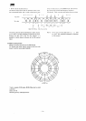
For the
Model
3500,
only
side
0 of
track
0
(128 bytes/sector)
is
written
in the FM
mode
and
rest
of
other
tracks
are
recorded
in the MFM
mode.
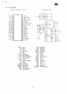
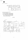
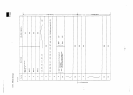
5-6.
I/O
port
in the MFD
interface
I/O
port
used
in the MFD
interface
is as
follows.
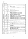
IOMF#F9-AO
IOMF#F8-AO
D-BUS
D7
D6
D5
D4
D3
1)2
1)1
DO
U2
Dl
DO
I/O
OUT
OUT
IN
DACK
ME
SCTRL
TC
TRIG
SEL3
SKI.
2
SEL1
SELO
M
. ON
I
NDEX
DRQ
Used
for
data transfer between
the CPU and the
FDC.
INT
from
the FDC is
output
enabled
on
INTFD.
FDD
select
signal
output
is
enabled.
TC
to
FDC.
Trigger
(motor
on) of the
timer (555)
Selects
FDD 3
Selects
FDD 2
Selects
FDD 1
Selects
FDDO
ON/OFF state
of the
motor
INDEX
signal
from
the
motor
DRO
from
the
FDC.
-
59-