


MZ
3500
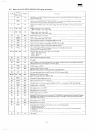
4-9.
VSYNC
0 40
Digit
From
1 80
Digu
(8255
PB7) CH48
SRES
(From
MMR)
40
digit. 16bu/word
80
digit,
8bit/word
Master
is GDC
40
digit, Sbit'word
Master
is GDC 1
80
digit,
16bit/word
Master
is
GDC-2
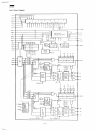
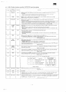
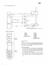
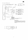
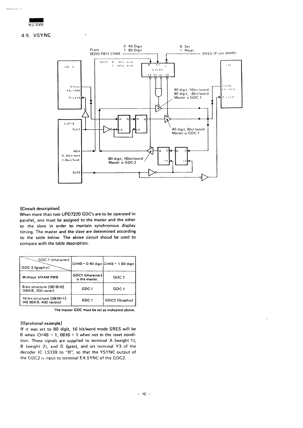
[Circuit
description]
When
more than
two
UPD7220 GDC's
are to be
operated
in
parallel,
one
must
be
assigned
to the
master
and the
other
to the
slave
in
order
to
mantain synchronous display
timing.
The
master
and the
slave
are
determined
according
to the
table below.
The
above
circuit
shoud
be
used
to
compare
with
the
table
description.
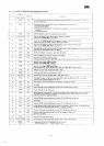
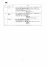
""~~~-~^GDC-1
(character)
GDC-2
(graphic)"""
^^^
Without
VRAM
PWB
8-bit
structure
[0816=0)
(48KB,
200
raster)
16-bit
structure
[0816=1]
(4896KB,
400
rasters)
CH48
= 0 40
digit
GDC1 (character)
is
the
master.
GDC1
GDC1
CH48
= 1 80
digit
GDC 1
GDC 1
GDC2 (Graphic)
The
master
GDC
must
be set as
indicated
above.
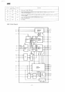
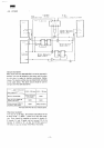
[Oprational example]
If it was set to 80
digit,
16
bit/word
mode
SRES
will
be
0
when CH48
= 1,
0816
= 1
when
not in the
reset
condi-
tion.
These
signals
are
supplied
to
terminal
A
(weight
1),
B
(weight
2), and G
(gate),
and set
terminal
Y3 of the
decoder
1C
LS139
to
"0",
so
that
the
YSYNC
output
of
the
GDC2
is
input
to
terminal
EX
SYNC
of the
GDC2.
-
46-