


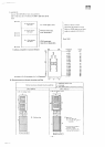
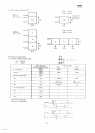

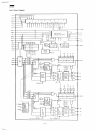
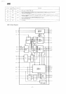

MZ3500
4/6.
Master
slice
LSI
(CSP-1)
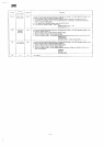
SP6102C
002
signal
description
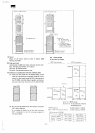
1
2
3
4-6
7-9
10
11
12
13
14
15
16-18
19
20.21
22
23
24
25
26-28
29
30
31
32
33
34
35
36
37
38
39
40
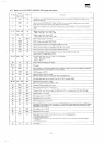
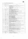
Priority
Signal
Name
HSYi
NABC
CSR
ASO
-
AS2
DSO
-
DS2
G2
NWRO
NVB
NVR
NVB
FYD2
AT2
-
AT4
CH
GND
DSP2
VID2
LCD
AT1
LC1
-
LC3
NCL4
HSYO
RA40
VIDI
B1
R1
Of
SL1
B2
R2
BLNK
Vcc
IN
IN
IN
IN
IN
OUT
IN
IN
IN
IN
IN
IN
IN
IN
IN
OUT
OUT
IN
OUT
OUT
OUT
OUT
OUT
OUT
OUT
OUT
IN
OUT
OUT
IN
IN
Horizontal
synchronizing
signal
from
the
GDC1
Also,
it
becomes
the
refresh
timing
signal
in the
dynamic
RAM
mode.
Input
from
the
UPD7220
GDC1. When
the
GDC1
is in the
character
display
mode,
the
attribute,
blinking timing
and
line
counter
ciear
signals
are
multiplexed.
Input
from
the
GDC1 which
is the
cursor
display
input when
the
GDC1
is in the
character
display
mode.
Address
bus
input
from
the
sub-CPU.
ABO
=
ASO,
AB1 = AS1 , AB2 = AS2
Data
bus
input
from
the
sub-CPU.
DBO
=
DBO,
DB1 = DB1 , DB2 = DB2
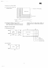
Green
image
output
to the
CRT2.
CSP1
I/O
port
select
signal
(OUT #5X)
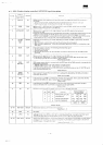
Input
of the
blue image from
the
graphic
RAM(A)
and
(B).
Input
of the red
image from
the
graphic
RAM
(B), (C),
and
(D).
Input
of the
green
image
from
the
graphic
RAM (E) and
(F).
Input
of the
graphic
RAM
parallel/serial
conversion
1C
74LS166
shift
out
clock.
(Used
to
latch
the
image
data
in
CSP1
.)
Attribute
data
input
from
the 21
14A-1
attribute
RAM.
f
AT-2
-
Horizontal Ime/R
"]
AT-3
-
Reverse/G
|_AT-4
-
Blink
J
Input
of
character display data signal.
0V
supply
Input
of
display
timing
signal supplied from
the
CSP-2.
(BLINK signal
from
the
GDC2
is
delayed
by
two
flipflop
intervals
in the
CSP-2
to
creat
this
signal.)
VIDEO
output
to
CRT2.
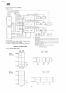
Character
CG
line counter
output.
(Becomes
address
input
to the CG
when
LCD = CG
address AO.)
Attribute
data
input
(vertical line/B)
from
the
2114A-1 attribute RAM.
Character
CG
line
counter
output.
(LC1
= A1, LC2 = A2, LC3 =
A3CG
= A3)
Character
CG
output
data latch
timing.
CRT1
, 2
horizontal
synchronizing
signal
The
signal that turns high
level
when
the
400-raster
CRT is in
connection. LDA,
01 H
OUT??56
VIDEO
output
to the
CRT1
.
Blue image
output
to the
CRT1
.
Red
image
output
to the
CRT1.
Green
image
output
to the
CRT1.
Character
CG
output
parallel/serial converter
1C
74LS166
shift
load
signal,
and
character
CG
address
latch
signal
input.
(Used
for the
image data latch signal
in the
CSP-1
and
horizontal synchronizing
signal
delay
flipflop
clock.)
Blue image
output
to
CRT2.
Red
image
output
to
CRT2.
Erase
signal from
the
GDC1 which
becomes
input
at the
following
times.
1.
Horizontal flyback period
2.
Vertical flyback period
3.
Period from
the
execution
of the
SYNC
SET
command
to the
execution
of the
DISP
START
command.
4.
Line drawing period
+5V
supply.
-
39
-