


M
Z
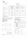
3500
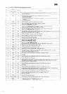
Pin
No
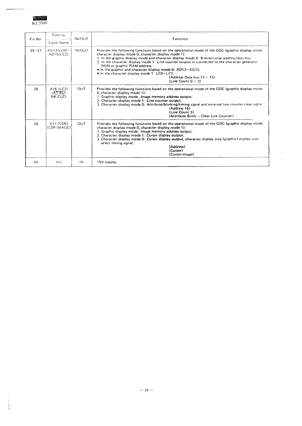
35-37
38
39
40
Polar,
ty
Signal
Name
AD13ILCO)-
AD15ILC2)
A16
(LC3)
(AT~BTI
NK-CLC)
A17
(CSR)
(CSR-1MAGE)
Vcc
IN/OUT
IN/OUT
OUT
OUT
IN
Function
Provides
the
following functions
based
on the
operational mode
of the GDC
(graphic display
mode,
character
display mode
0,
character
display mode
1).
1.
In the
graphic display mode
and
character display mode
0:
Bidirectional
address/data
bus
2.
In the
character
display mode
1 :
Line counter
output
in
connected
to the
character
generator
ROM
or
graphic
RAM
address.
• In the
graphic
and
character display mode
0:
AD13~AD1
5.
• In the
character
display mode
1 :
LCO~LC1.
(Address
Data
bus 13 ~ 15)
(Line
Count
0-2)
Provides
the
following
functions
based
on the
operational mode
of the GDC
(graphic display mode.
0.
character
display
mode
1 ):
1.
Graphic display
mode:
Image memory address
output.
2.
Character
display mode
1 :
Line
counter
output.
3.
Character
display mode
0:
Attribute/blinking/timing
signal
and
external
line counter
clear
signal
(Address
16}
(Line
Count
3)
(Attribute
Blink
—
Clear Lire Counter)
Provides
the
following
functions
based
on the
operational mode
of the GDC
(graphic display mode,
character
display mode
0,
character display
mode
1):
1.
Graphic display mode: Image memory address
output.
2.
Character
display
mode
1 :
Cursor
display
output.
3.
Character
display mode
0:
Cursor
display
output,
character display
area
(graphic)
display
area
select
timing
signal.
(Address)
(Cursor)
(Cursor-image)
+
5V
supply.
-
-14
-