In the
case
of the MFM
method, need
to
trace
cycle
fluc-
tuation
is
further
increased,
as a
peak
shift
is apt to
occur
because
there
are
three
write
data
cycles.
(Peak
shift).
Data
read
cycles
fluctuate
as the
flux
change
point
is
moved
forwards
or
backwards.
Write
pulse
Polarity
inversion
Read
waveform
MZ
3500
Advanced
peak
shift
-
Regenerated
pulse
H
*—
Delayed
peak
shift
Cb)
{VFO
circuit):
Variable frequency oscillator
Polarity
inversion
f~J
Polarity
inversion
Write
pulse
J
Read
waveform
6.0
40 20 0 20 40 60
(a)
j
I I
Advanced
peak
shift
—-| t— —•) j*-
Delayed
peak
shift
(c)
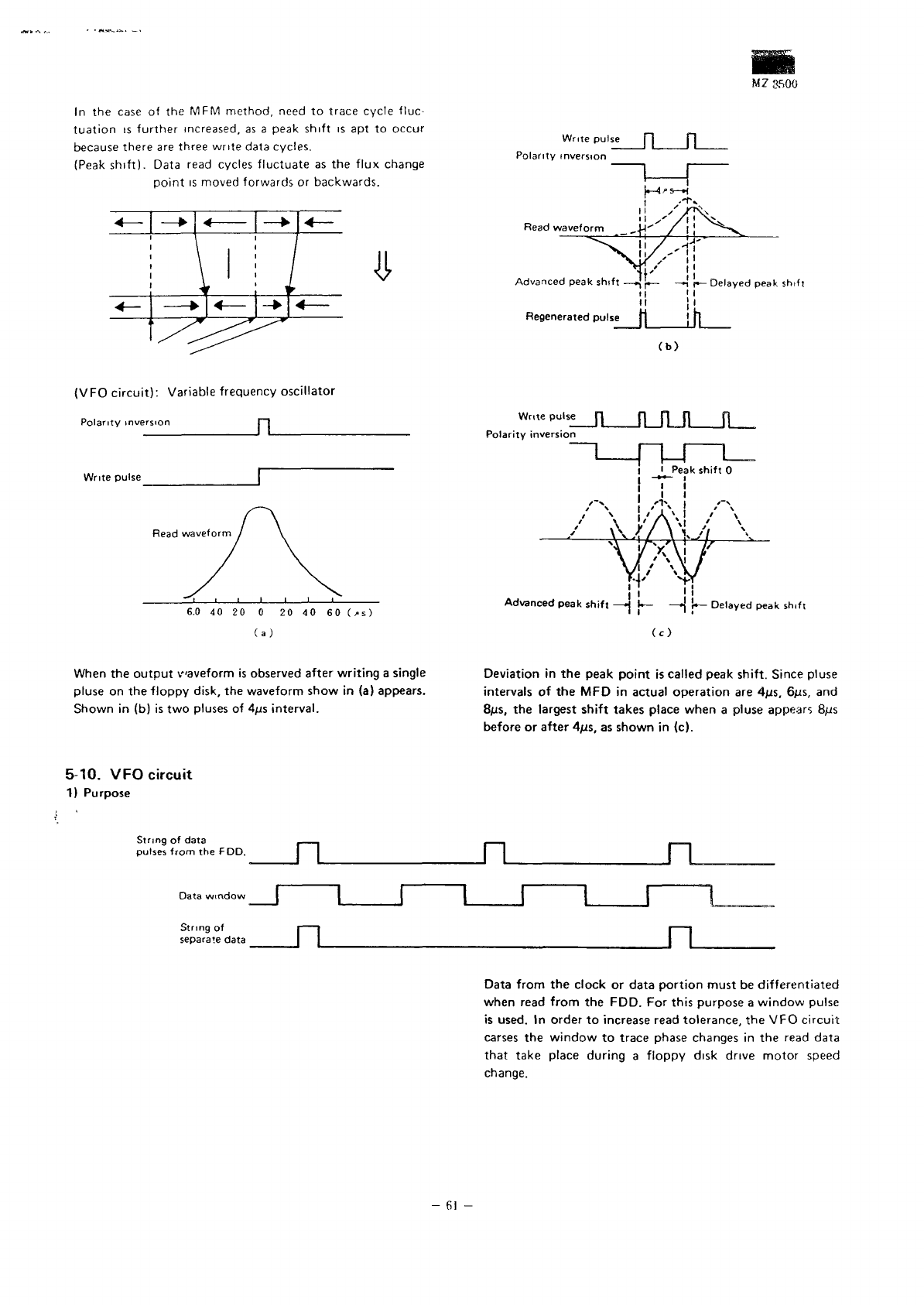
When
the
output
waveform
is
observed after
writing
a
single
pluse
on the
floppy
disk,
the
waveform
show
in (a)
appears.
Shown
in (b) is two
pluses
of
4jis
interval.
Deviation
in the
peak
point
is
called
peak
shift.
Since pluse
intervals
of the MFD in
actual
operation
are
4ns, 6/JS,
and
8/^s,
the
largest
shift
takes place
when
a
pluse appears 8/Js
before
or
after
4/JS,
as
shown
in
(c).
5-10.
VFO
circuit
1)
Purpose
String
of
data
pulses
from
the
FDD.
Data
window
String
of
separate
data
n
n
Data
from
the
clock
or
data
portion
must
be
differentiated
when
read
from
the
FDD.
For
this
purpose
a
window
pulse
is
used.
In
order
to
increase read
tolerance,
the VFO
circuit
carses
the
window
to
trace phase
changes
in the
read
data
that
take place
during
a
floppy
disk drive
motor
speed
change.
-
61
-


