


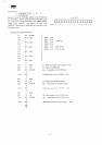
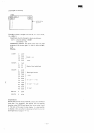
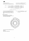
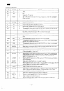
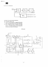
MZ3500
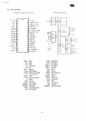
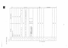
UPD765
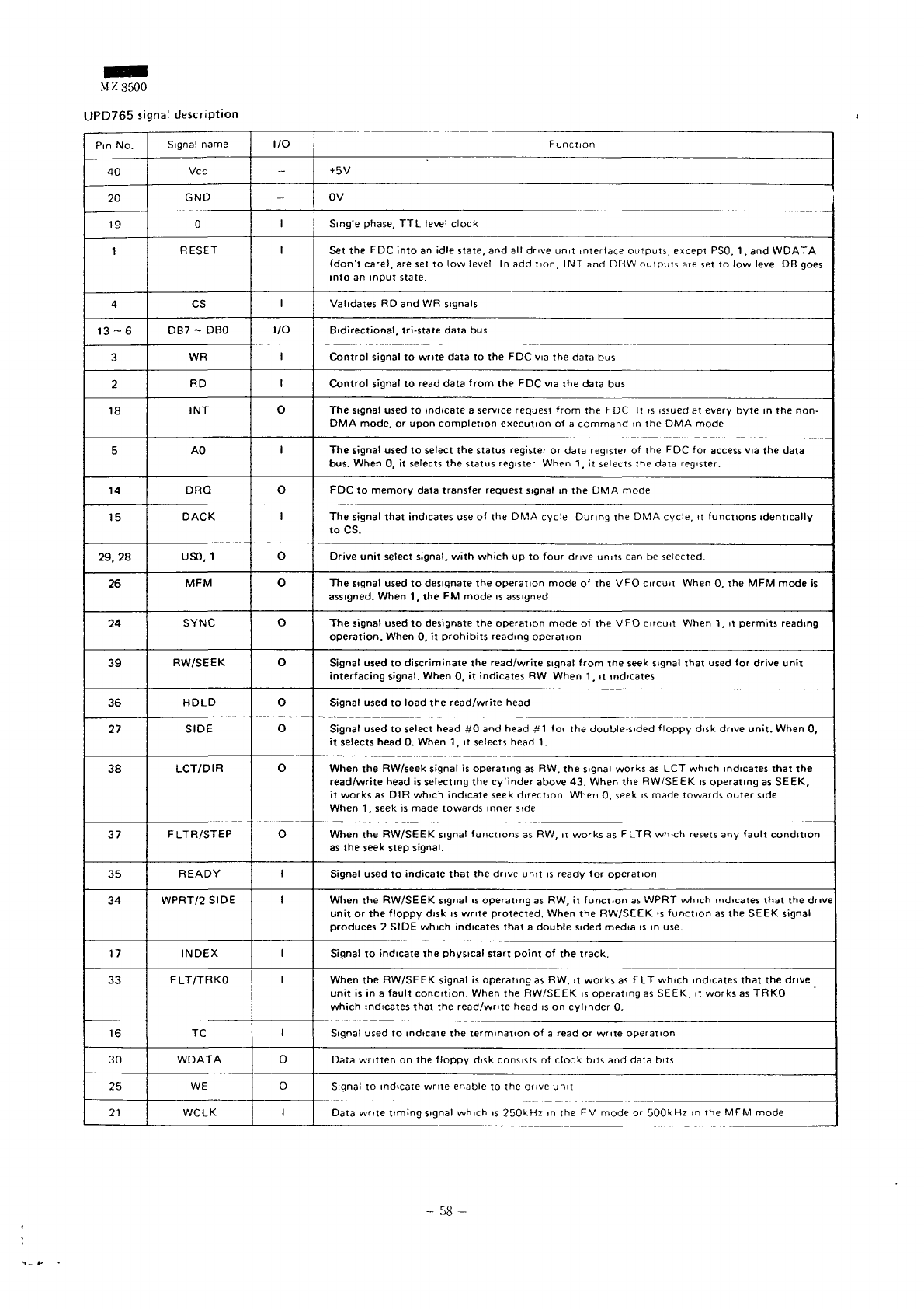
signal
description
Pin
No.
40
20
19
1
4
13-6
3
2
18
5
14
15
29,28
26
24
39
36
27
38
37
35
34
17
33
16
30
25
21
Signal
name
Vcc
GND
0
RESET
CS
DB7
~ DBO
WR
RD
INT
AO
DRQ
DACK
USD,
1
MFM
SYNC
RW/SEEK
HOLD
SIDE
LCT/DIR
FLTR/STEP
READY
WPRT/2
SIDE
INDEX
FLT/TRKO
TC
WDATA
WE
WCLK
I/O
-
-
I
1
1
I/O
'
1
o
1
o
1
0
o
o
o
0
0
0
o
1
1
'
1
1
0
o
1
Function
+5V
0V i
Single phase,
TTL
level
clock
Set
the FDC
into
an
idle
state,
and all
drive
unit
interface
outputs,
except
PSO,
1 , and
WDATA
(don't
care),
are set to low
level
In
addition,
INT and DRW
outputs
are set to low
level
DB
goes
into
an
input
state.
Validates
RD and WR
signals
Bidirectional,
tri-state data
bus
Control
signal
to
write
data
to the FDC via the
data
bus
Control
signal
to
read data
from
the FDC via the
data
bus
The
signal used
to
indicate
a
service
request
from
the FDC It is
issued
at
every
byte
in the
non-
DMA
mode,
or
upon
completion
execution
of a
command
in the DMA
mode
The
signal used
to
select
the
status
register
or
data
register
of the FDC for
access
via the
data
bus. When
0, it
selects
the
status
register
When
1. it
selects
the
data
register.
FDC
to
memory
data transfer request signal
in the DMA
mode
The
signal that indicates
use of the DMA
cycle
During
the DMA
cycle,
it
functions identically
toCS.
Drive
unit
select signal,
with
which
up to
four drive units
can be
selected.
The
signal used
to
designate
the
operation mode
of the VFO
circuit When
0, the MFM
mode
is
assigned.
When
1, the FM
mode
is
assigned
The
signal
used
to
designate
the
operation
mode
of the VFO
circuit
When
1, it
permits
reading
operation.
When
0, it
prohibits
reading operation
Signal
used
to
discriminate
the
read/write signal
from
the
seek
signal
that
used
for
drive
unit
interfacing
signal. When
0, it
indicates
RW
When
1 , it
indicates
Signal used
to
load
the
read/write head
Signal used
to
select head
#0 and
head
#1 for the
double-sided floppy disk drive
unit.
When
0,
it
selects head
0.
When
1, it
selects
head
1.
When
the
RW/seek signal
is
operating
as RW, the
signal
works
as LCT
which indicates
that
the
read/write
head
is
selecting
the
cylinder
above
43.
When
the
RW/SEEK
is
operating
as
SEEK,
it
works
as DIR
which indicate
seek
direction When
0.
seek
is
made towards outer side
When
1,
seek
is
made towards inner
side
When
the
RW/SEEK signal functions
as RW, it
works
as F LTR
which
resets
any
fault
condition
as
the
seek
step signal.
Signal used
to
indicate
that
the
drive
unit
is
ready
for
operation
When
the
RW/SEEK signal
is
operating
as RW, it
function
as
WPRT which indicates
that
the
drive
unit
or the
floppy
disk
is
write protected. When
the
RW/SEEK
is
function
as the
SEEK signal
produces
2
SIDE
which
indicates that
a
double
sided media
is in
use.
Signal
to
indicate
the
physical start
point
of the
track.
When
the
RW/SEEK signal
is
operating
as RW. it
works
as FLT
which
indicates
that
the
drive
unit
is in a
fault
condition.
When
the
RW/SEEK
is
operating
as
SEEK,
it
works
as
TRKO
which
indicates
that
the
read/write head
is on
cylinder
0.
Signal
used
to
indicate
the
termination
of a
read
or
write
operation
Data
written
on the
floppy
disk
consists
of
clock bits
and
data
bits
Signal
to
indicate write
enable
to the
drive
unit
Data
write
timing
signal
which
is
250kHz
in the FM
mode
or
500kHz
in the MFM
mode
-
58-