


Triggering on Waveforms
3–64
TDS 500C, TDS 600B, & TDS 700C User Manual
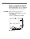
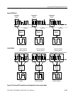
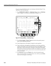
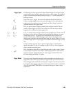
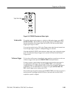
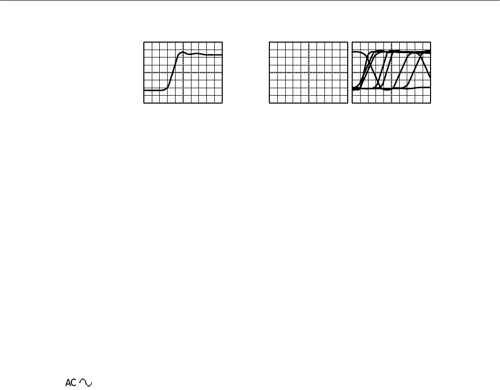
Triggered Waveform Untriggered Waveforms
Figure 3–32: Triggered Versus Untriggered Displays
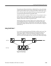
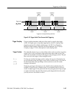
The trigger event establishes the time-zero point in the waveform record. All
points in the record are located in time with respect to that point. The oscillo-
scope continuously acquires and retains enough sample points to fill the
pretrigger portion of the waveform record (that part of the waveform that is
displayed before, or to the left of, the triggering event on screen). When a trigger
event occurs, the oscilloscope starts acquiring samples to build the posttrigger
portion of the waveform record (displayed after, or to the right of, the trigger
event). Once a trigger is recognized, the digitizing oscilloscope will not accept
another trigger until the acquisition is complete.
You can derive your trigger from the following sources:
Input channels provide the most commonly used trigger source. You can select
any one of the four input channels. The channel you select as a trigger source
will function whether it is displayed or not.
AC Line Voltage is the trigger source most often used when you are looking at
signals related to the power line frequency. Examples include devices such as
lighting equipment and power supplies. Because the oscilloscope generates the
trigger, you do not have to input a signal to create the trigger.
Auxiliary Trigger is the trigger source most often used in doing digital design
and repair. For example, you might want to trigger with an external clock or with
a signal from another part of the circuit. To use the auxiliary trigger, connect the
external triggering signal to the Auxiliary Trigger input connector on the
oscilloscope rear panel.
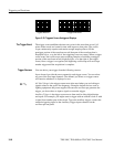
The Trigger Event
Trigger Sources