Triggering on Waveforms
TDS 500C, TDS 600B, & TDS 700C User Manual
3–71
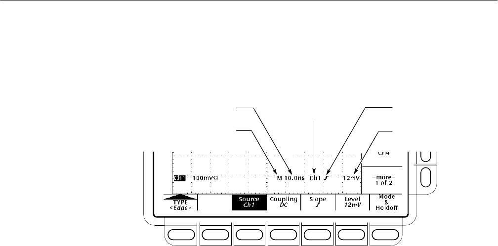
Trigger Readout. To quickly determine the settings of some key trigger parame-
ters, check the Trigger readout at the bottom of the display. (See Figure 3–36.)
The readouts differ for edge, logic, and pulse triggers.
Main Time Base
Main Time Base Time/Div
Main Trigger
Source = Ch 1
Main Trigger
Slope = Rising Edge
Main Trigger
Level
Figure 3–36: Example Trigger Readouts — Edge Trigger Selected
Record View. To determine where the trigger point is located in the waveform
record and with respect to the display, check the record view at the top of the
display. (See Figure 3–37.)
Trigger Position and Level Indicators. To see the trigger point and level on the
waveform display, check the graphic indicators Trigger Position and Trigger Bar.
Figure 3–37 shows the trigger point indicator and trigger level bar.
Both the trigger point indicator and level bar are displayed from the Display
menu. See Set Display Readout Options on page 3–40 for more information.
The trigger point indicator shows position. It can be positioned horizontally off
screen, especially with long record length settings. The trigger level bar shows
only the trigger level. It remains on screen, regardless of the horizontal position,
as long as the channel providing the trigger source is displayed.
Trigger Status Screen. To see a more comprehensive status listing of the settings
for the main and delayed trigger systems, press SHIFT STATUS ➞ STA-
TUS (main) ➞ Trigger (side).


