Using Features for Advanced Applications
TDS 500C, TDS 600B, & TDS 700C User Manual
3–205
To measure the phase relative to most source waveforms, you need only to center
the positive peak around the zero phase point. (For instance, center the positive
half cycle for a sine or square wave around the zero phase point.) Use the
following method:
H First be sure the FFT math waveform is selected in the More menu, then set
horizontal position to 50% in the Horizontal menu. This positions the zero
phase reference point to the horizontal center of the screen.
H In the Horizontal menu, vary the trigger position to center the positive peak
of the source waveform at the horizontal center of screen. Alternately, you
can adjust the trigger level (knob) to bring the positive peak to center screen
if the phase reference waveform has slow enough edges.
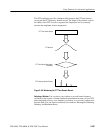
When impulse testing and measuring phase, align the impulse input into the
system to the zero reference point of the FFT time domain waveform:
H Set the trigger position to 50% and horizontal position to 50% for all record
lengths less than 15 K.
H For records with a 100 K length, set the trigger position to 5%. Use the
horizontal position knob to move the trigger T on screen to the center
horizontal graticule line.
H Do not use the 15 K length, nor, if your oscilloscope model is so equipped,
and of the record lengths 30 K, 75 K, or 130 K to impulse test using FFTs.
These record lengths do not allow easy alignment of the zero reference point
for phase measurements.
H Trigger on the input impulse.
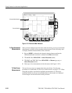
Adjust Phase Suppression. Your source waveform record may have a noise
component with phase angles that randomly vary from −pi to pi. This noise
could make the phase display unusable. In such a case, use phase suppression to
control the noise.


