103
6. COMMUNICATIONS SETUP AND OPERATION
The T803 is equipped with an Ethernet port, a USB port and two serial
communication (COM) ports (RS232 and COM2) located on the rear panel (see
Figure 3-2). Both COM ports operate similarly and give the user the ability to
communicate with, issue commands to, and receive data from the analyzer
through an external computer system or terminal.
This section provides pertinent information regarding communication equipment,
describes the instrument’s communications modes, presents configuration
instructions for the communications ports, and provides instructions for their use,
including communications protocol. Data acquisition is presented in Section 7.
By
default, both COM ports operate on the RS-232 protocol.
6.1. DATA TERMINAL/COMMUNICATION EQUIPMENT (DTE DCE)
RS-232 was developed for allowing communications between data terminal
equipment (DTE) and data communication equipment (DCE). Basic data
terminals always fall into the DTE category whereas modems are always
considered DCE devices.
Electronically, the difference between the DCE and DTE is the pin assignment of
the Data Receive and Data Transmit functions.
DTE devices receive data on Pin 2 and transmit data on Pin 3.
DCE devices receive data on Pin 3 and transmit data on Pin 2.
A switch located below the serial ports on the rear panel allows the user to switch
between DTE (for use with data terminals) or DCE (for use with modems). Since
computers can be either DTE or DCE, check your computer to determine which
mode to use.
6.2. COMMUNICATION MODES, BAUD RATE AND PORT
TESTING
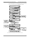
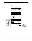
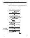
Use the SETUP>MORE>COMM menu to configure COM1 (labeled RS232 on
instrument rear panel) and/or COM2 (labeled COM2 on instrument rear panel)
for communication modes, baud rate and/or port testing for correct connection. If
using a USB option communication connection, setup requires downloading the
USB driver and configuring per Section 6.4.
6.2.1. COM PORT COMMUNICATION MODES
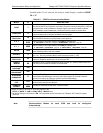
Each of the analyzer’s serial ports can be configured to operate in a number of
different modes, listed in Table 6-1. As modes are selected, the analyzer sums
the mode ID num
bers and displays this combined number on the front panel
display. For example, if quiet mode (01), computer mode (02) and Multi-Drop-
07276B DCN6418


