


Basic Operation Teledyne API T803 CO2/O2 Analyzer Operation Manual
58
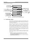
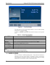
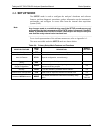
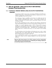
Figure 4-1: Front Panel Display
The mode field of the front panel display indicates to the user which operating
mode the unit is currently running.
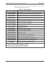
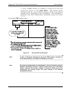
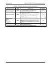
In addition to SAMPLE and SETUP, other modes the analyzer can be operated
in are:
Table 4-1: Analyzer Operating Modes
MODE DESCRIPTION
SAMPLE Sampling normally, flashing text indicates adaptive filter is on.
SAMPLE A
Indicates that unit is in Sample Mode while AUTOCAL feature is active.
CO2 M-P CAL This is the basic calibration mode of the instrument and is activated by pressing the CAL button.
SETUP [X.X]
SETUP mode is being used to configure the analyzer. The gas measurement will continue during this
process. The revision of the T803 firmware being run will appear after the word “SETUP”
CAL CO2 Z[type]
2 & 3
Unit is performing CO
2
ZERO calibration procedure.
CAL CO2 S[type]
2 & 3
Unit is performing CO
2
SPAN calibration procedure.
CAL O2 Z[type]
2 & 3
Unit is performing O
2
ZERO calibration procedure.
CAL O2 S[type]
2 & 3
Unit is performing O
2
SPAN calibration procedure.
DIAG Mode One of the analyzer’s diagnostic modes is active (Section 5.9).
[type:]
2
M: initiated manually by the user via the front panel touchscreen.
3
R: initiated remotely through the COM ports or digital control inputs.
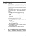
4.2. SAMPLE MODE
This is the analyzer’s standard operating mode. In this mode the instrument is
analyzing the gas in the sample chamber, calculating CO
2
and O
2
concentrations
and reporting this information to the user via the front panel display, the analog
outputs and, if set up properly, the RS-232/485/Ethernet ports.
07276B DCN6418