


Principles of Operation Teledyne API T803 CO2/O2 Analyzer Operation Manual
220
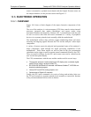
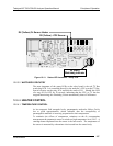
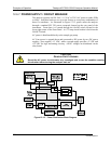
12.6.7. POWER SUPPLY / CIRCUIT BREAKER
The analyzer operates on 100 VAC, 115 VAC or 230 VAC power at either 50Hz
or 60Hz. Individual units are set up at the factory to accept any combination of
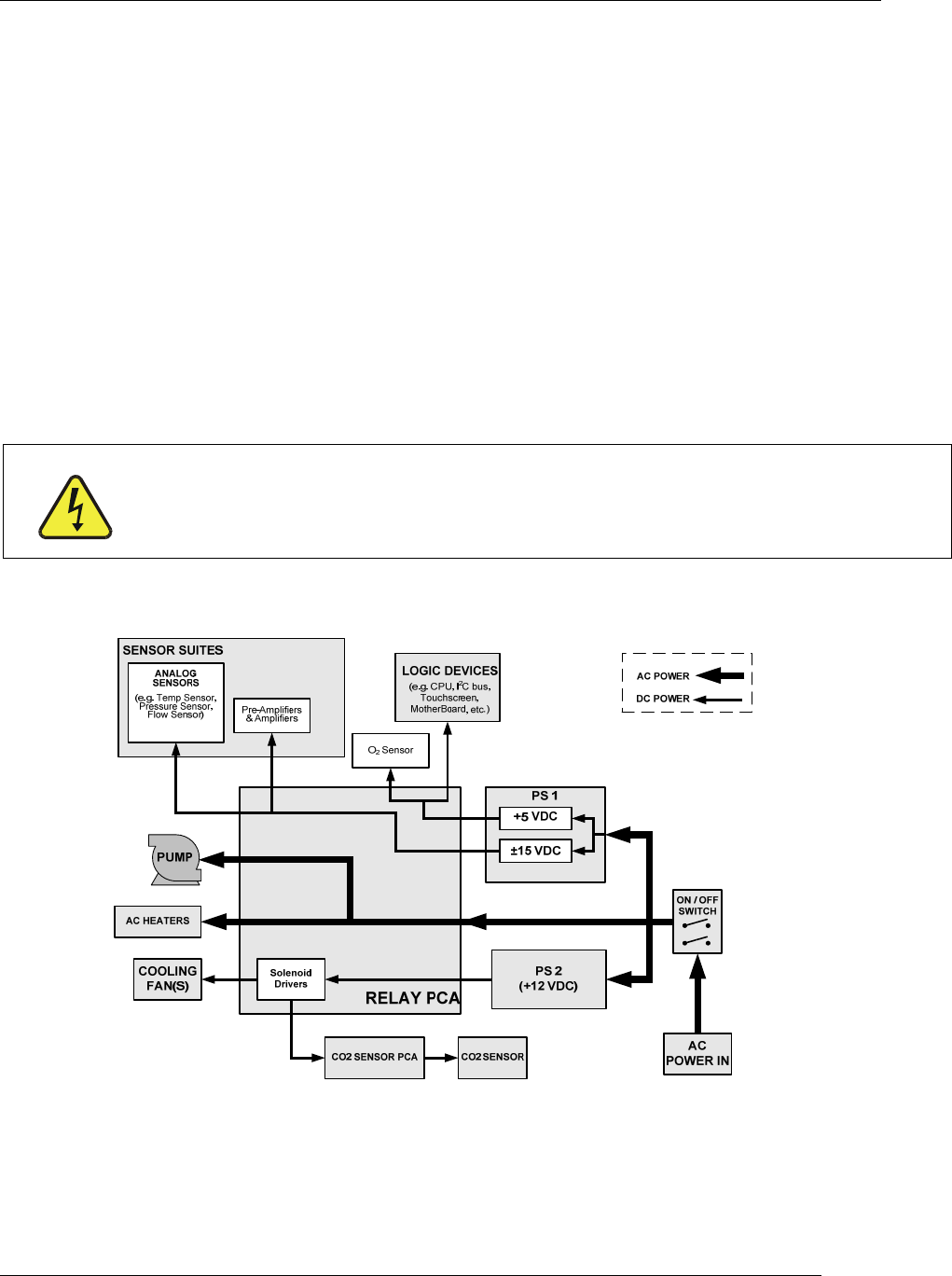
these five attributes. As illustrated in Figure 12-12, power enters the analyzer
through a standard IEC 3
20 power receptacle located on the rear panel of the
instrument. From there it is routed through the On/Off switch located in the
lower right corner of the Front Panel. A 6.75 Amp circuit breaker is built into the
ON/OFF Switch.
AC power is distributed directly to the sample gas pump.
AC Line power is stepped down and converted to DC power by two DC power
supplies. One supplies +12 VDC, while a second supply provides +5 VDC and
±15 VDC for logic and analog circuitry. All DC voltages are distributed via the
relay board.
CAUTION
GENERAL SAFETY HAZARD
Should the AC power circuit breaker trip, investigate and correct the condition causing
this situation before turning the analyzer back on.
Figure 12-12: Power Distribution Block Diagram
07276B DCN6418