


Teledyne API T803 CO2/O2 Analyzer Operation Manual Principles of Operation
213
Flow/Pressure Sensor PCA
CO
2
Sensor
Heater
Analog Outputs
Aout 1
Aout 4
Analog Outputs
(D/A)
External Digital I/O
Power Up
Circuit
P
C
1
0
4
B
u
s
PC 104
CPU Card
Disk on
Module
Flash
Chip
Aout 3
Aout 2
TEST CHANNEL OUTPUT
Status
Outputs
1 - 8
Control
Outputs
1 – 6
Optional
Current
Loop
Outputs
CPU
Status
LED
I
2
C Bus
O
2
Cell
Heater
Thermistor Interface
Box
Temperature
Sample Flow
Sensor
A/D
Converter
RELAY PCA
I
2
C
Status
LED
CO
2
Range 2
CO
2
Range 1
MOTHERBOARD
Sample Pressure
Sensor
Sensor Inputs
O
2
O
2
Sensor
CO
2
Sensor
Internal
Digital I/O
O
2
Concentration
O
2
Sensor
Temperature
CO
2
Sensor
Temperature
BOX
Temperature
COM2
Female
RS232
Male
Ethernet
USB COM
port
ANALOG
IN
(
I
2
C Bus
)
COM1 (RS-232 only)
COM2 (RS-232 or RS-485)
or USB
Touchscreen
Dis
p
la
y
LVDS
transmitter
board
USB
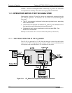
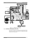
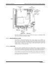
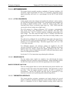
Figure 12-7: T803 Electronic Block Diagram
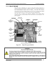
12.6.2. CENTRAL PROCESSING UNIT (CPU)
The unit’s CPU card (Figure 12-8) is installed on the motherboard located inside
the rear panel. It is a low power (5 VDC, 720mA max), high performance, Vortex
86SX-based microcomputer running Windows CE. Its operation and assembly
conform to the PC/104 specification.
07276B DCN6418