


Troubleshooting and Service Teledyne API T803 CO2/O2 Analyzer Operation Manual
186
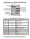
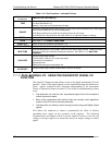
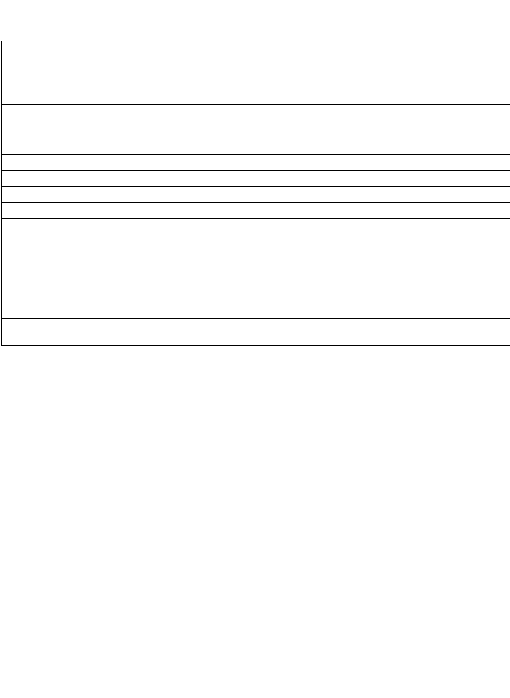
Table 11-2: Test Functions - Indicated Failures
TEST FUNCTIONS
(As Displayed)
INDICATED FAILURE(S)
TIME
Time of day clock is too fast or slow
To adjust See Section 5.6.
Battery
in clock chip on CPU board may be dead.
RANGE
Incorrectly configured measurement range(s) could cause response problems with a Data logger or
chart recorder attached to one of the analog output.
If the Range selected is too small, the recording device will over range.
If the Range is too big, the device will show minimal or no apparent change in readings.
STABIL
Indicates noise level of instrument or concentration of sample gas (See Section 11.3 for causes).
PRES
See Table 11-1 for SAMPLE PRES WARN
SAMPLE FL
Check for gas flow problems (see Section 11.3).
O2 CELL TEMP
Temperatures outside of the specified range or oscillating temperatures are cause for concern
BOX TEMP
If the box temperature is out of range, check fan in the power supply module. Areas to the side
and rear of instrument should allow adequate ventilation. See Table 11-1 for BOX TEMP
WAR
NING.
O2 SLOPE
Values outside range indicate
Contamination of the zero air or span gas supply
Instrument is miscalibrated
Blocked gas flow
Bad/incorrect span gas concentration due.
O2 OFFSET
Values outside range indicate contamination of the zero air supply
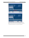
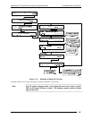
11.1.3. DIAG SIGNAL I/O: USING THE DIAGNOSTIC SIGNAL I/O
FUNCTION
The signal I/O diagnostic mode allows access to the digital and analog I/O in the
analyzer. Some of the digital signals can be controlled through the touchscreen.
These signals, combined with a thorough understanding of the instruments
Theory of Operation (found in Section 12), are useful for troubleshooting in three
ways
:
The technician can view the raw, unprocessed signal level of the analyzer’s
critical inputs and outputs.
Many of the components and functions that are normally under algorithmic
control of the CPU can be manually exercised.
The technician can directly control the signal level Analog and Digital Output
signals.
This allows the technician to observe systematically the effect of directly
controlling these signals on the operation of the analyzer. The following
flowchart shows an example of how to use the Signal I/O menu to view the raw
voltage of an input signal or to control the state of an output voltage or control
signal.
07276B DCN6418