


Teledyne API T803 CO2/O2 Analyzer Operation Manual Setup Menu
65
5.4.2. ANALOG OUTPUT RANGES FOR CO
2
AND O
2
CONCENTRATION
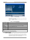
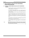
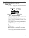
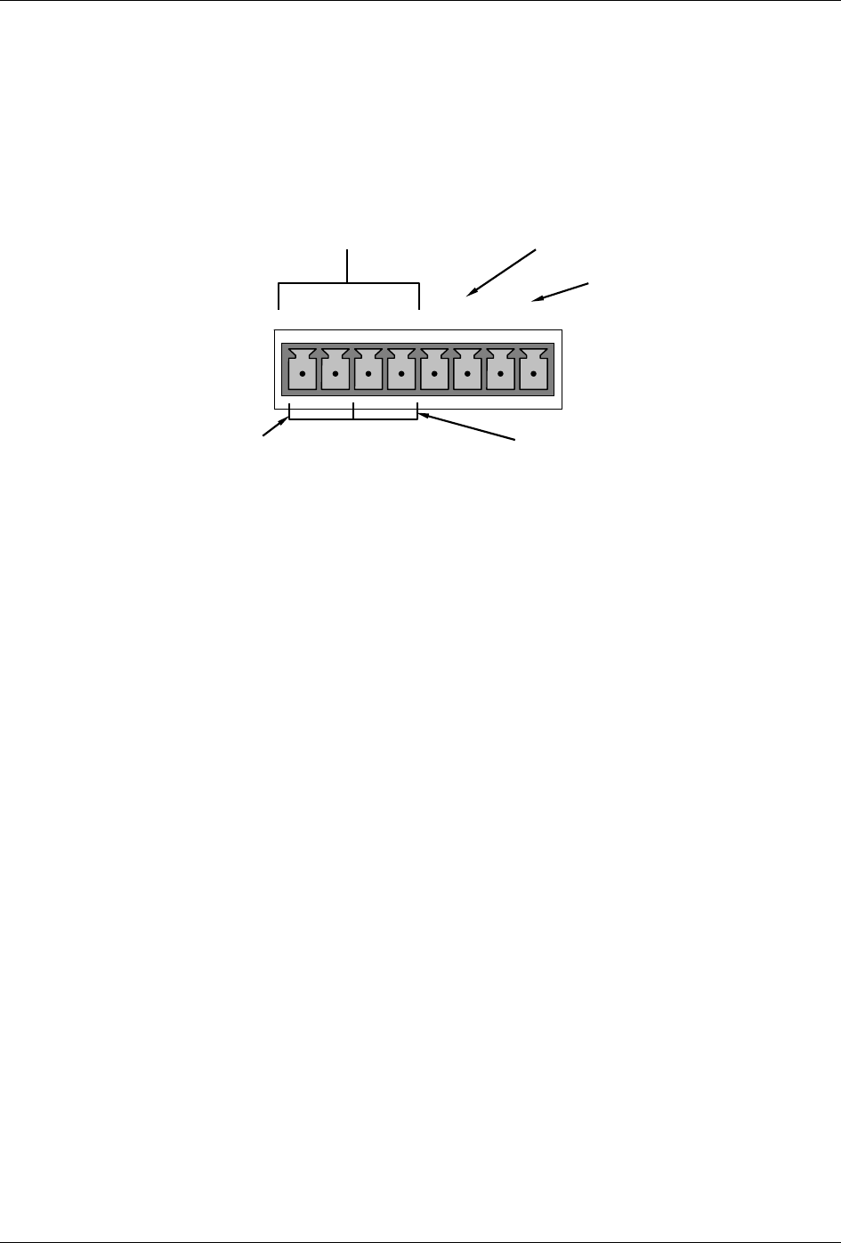
The analyzer has several active analog output signals accessible through a
connector on the rear panel (see Figure 3-4).
O
2
concentration output
A
NALOG OUT
A1 A2
A
3
A
4
+ - + - + - + -
CO
2
concentration outputs
HIGH range when DUAL
or AUTO mode is selected
Test Channel
LOW range when DUAL
or AUTO mode is selected
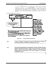
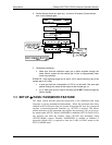
Figure 5-1: Analog Output Connector Pin Out
All three outputs can be configured either at the factory or by the user for full
scale outputs of 0.1 VDC, 1VDC, 5VDC or 10VDC.
Additionally A1, A2 and A3 may be equipped with optional 0-20 mA current
loop drivers and configured for any current output within that range (e.g. 0-20, 2-
20, 4-20, etc.). The user may also adjust the signal level and scaling of the actual
output voltage or current to match the input requirements of the recorder or
datalogger (See Section 5.10.5).
When the instrument is in
its default configuration, channels A1 and A2 (Dual or
Auto range) output a signal proportional to the CO
2
concentration of the sample
gas.(See Section 5.4.3).
Channel A3 outputs a sign
al proportional to the O
2
concentration of the sample
gas.
EXAMPLE:
A1 OUTPUT: Output Signal = 0-5 VDC representing 0- 20 % CO2
concentration values
A3 OUTPUT: Output Signal = 0 – 10 VDC representing 0-100 % O
2
concentration
values.
The output, labeled A4 is special. It can be set by the user (See Section 5.10.6) to
output several of the test functions accessible through the <TST TST> buttons of
the units sample display.
07276B DCN6418