


Getting Started Teledyne API T803 CO2/O2 Analyzer Operation Manual
36
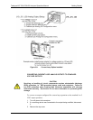
a) Remove the set screw located at the top center of the rear panel
b) Remove the screws fastening the top cover to the unit (two per side).
c) Slide cover back.
d) Lift the cover straight up.
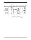
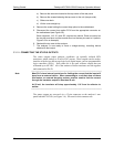
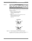
4. Remove the screw holding the current loop option to the motherboard.
5. Disconnect the current loop option PCA from the appropriate connector on
the motherboard (see Figure 3-8).
Each
connector, J19, J21 and J23, requires two shunts. Place one shunt on
the two left most pins and the second shunt on the two pins next to it (refer to
Figure 3-8 for an example).
6. Reatta
ch the top case to the analyzer.
7. The analyzer is now ready to have a voltage-sensing, recording device
attached to that output.
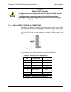
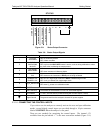
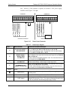
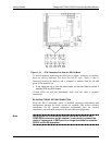
3.3.1.5. CONNECTING THE STATUS OUTPUTS
The status outputs report analyzer conditions via optically isolated NPN
transistors, which sink up to 50 mA of DC current. These outputs can be used to
interface with devices that accept logic-level digital inputs, such as programmable
logic controllers (PLCs). Each status bit is an open collector output that can
withstand up to 40 VDC. All of the emitters of these transistors are tied together
and connected at Pin D.
Note
Most PLCs have internal provisions for limiting the current that the input will
draw from an external device. When connecting to a unit that does not have
this feature, an external dropping resistor must be used to limit the current
through the transistor output to less than 50 mA.
At 50 mA, the transistor will drop approximately 1.2V from its collector to
emitter.
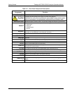
The status outputs are accessed via a 12-pin connector on the analyzer’s rear
panel labeled STATUS (see Figure 3-4). Pin-outs for this connector are:
07276B DCN6418