


Teledyne API T803 CO2/O2 Analyzer Operation Manual Getting Started
37
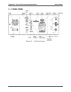
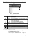
STATUS
1 2 3 4 5 6 7 8 D
+
SYSTEM OK
CONC VALID
CAL MODE / MEAS MODE
SPAN CAL / ZERO MODE
CAL MODE – RANGE 2
CO
2
CAL
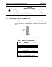
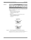
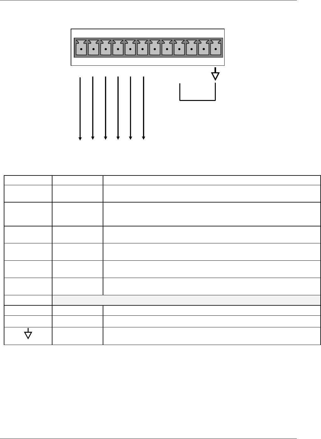
Figure 3-9: Status Output Connector
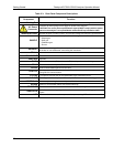
Table 3-6: Status Output Signals
Rear Panel Label Status Definition Condition
1
SYSTEM
OK/ALARM
ON if no faults are present.
OFF if alarm condition
2
CONC
VALID/CONC
INVALID
ON if concentration measurement is valid.
OFF any time the HOLD OFF feature is active, such as during calibration or when
any faults exist invalidating the measurement.
3
CAL MODE/
MEAS MODE
ON whenever the instrument is in Calibration Mode
OFF when instrument in Measure Mode
4
SPAN/ZERO
CAL
ON whenever the instrument’s SPAN point is being calibrated.
OFF whenever the instrument’s ZERO point is being calibrated.
5
RANGE2 CAL
RANGE1 CAL
ON if unit is in high range of either the DUAL or AUTO range modes.
OFF if unit is in default low, single range mode
6
C
O
2
/O
2
Sensor CAL
ON when CO
2
sensor is in calibration mode.
OFF when O
2
sensor is in calibration mode.
7 & 8
SPARE
D
EMITTER BUS The emitters of the transistors on Pins 1-8 are bussed together.
+
DC POWER + 5 VDC, 300 mA source (combined rating with Control Output, if used).
Digital Ground The ground level from the analyzer’s internal DC power supplies
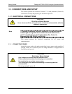
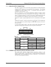
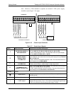
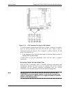
3.3.1.6. CONNECTING THE CONTROL INPUTS
If you wish to use the analyzer to remotely activate the zero and span calibration
modes, several digital control inputs are provided through a 10-pin connector
labeled CONTROL IN on the analyzer’s rear panel.
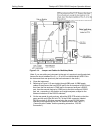
There are two methods for energizing the control inputs. The internal +5V
available from the pin labeled “+” is the most convenient method (Figure 3-10,
07276B DCN6418