Getting Started Teledyne API T803 CO2/O2 Analyzer Operation Manual
38
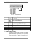
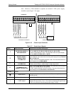
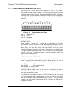
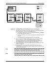
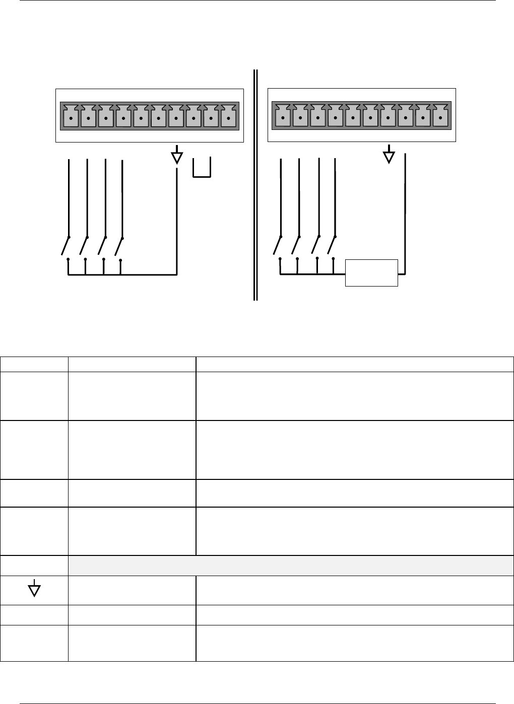
left). However, if full isolation is required, an external 5 VDC power supply
should be used (Figure 3-10, right).
CONTROL IN
A B C D E F U
+
SPAN/ZERO CAL
CAL/MEAS MODE
CONTROL IN
A B C D E F U
+
-
+
5 VDC
Power Supply
Local Power Connections
External Power Connections
RANGE SELECTION
O2/CO2 CAL
SPAN/ZERO CAL
CAL/MEAS MODE
RANGE SELECTION
O2/CO2 CAL
Figure 3-10: Control Input Connector
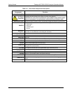
Table 3-7: Control Input Signals
Input # Status Definition Open/Closed Condition Description
A
CALIBRATION MODE or
MEASURE MODE
Open: initiates Calibration mode. The mode field of the front panel display
will read CO2 CAL R, CO2 CAL ZR, O2 CAL R or O2 CAL ZR
Closed: initiates Measure mode. The mode field of the front panel display
will read CO2 R, CO2 ZR, O2 R, or O2 ZR
B
REMOTE SPAN or
REMOTE ZERO
CALIBRATION
Open: initiates remote SPAN calibration mode as part of performing a low
span calibration. The mode field of the front panel display will read CO2 CAL
SR or O2 CAL SR.
Closed: initiates remote ZERO calibration mode. The mode field of the front
panel display will read ZERO MODE.
C
RANGE2 or RANGE1
CALIBRATION
Open: selects Range 2 for calibration.
Closed: selects Range 1, default range in single range mode.
D
O
2
SENSOR or CO
2
SENSOR CALIBRATION
Open: initiates calibration of the O
2
sensor. The mode field of the front panel
display will read O2 CAL R or O2 CAL ZR.
Closed: Initiates calibration of the CO
2
sensor. The mode field of the front
panel display will read CO2 CAL R or CO2 CAL ZR
E & F
SPARE
Digital Ground
The ground level from the analyzer’s internal DC power supplies (same as
chassis ground)
U
External Power input Input pin for +5 VDC required to activate Pins A – F.
+
5 VDC output
Internally generated 5V DC power. To activate inputs A – F, place a jumper
between this pin and the “U” pin. The maximum amperage through this port
is 300 mA (combined with the analog output supply, if used).
07276B DCN6418


