


Getting Started Teledyne API T803 CO2/O2 Analyzer Operation Manual
48
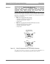
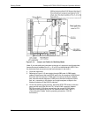
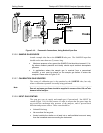
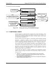
Calibrated N
2
100%
Concentration
Calibrated gas
(O
2
at 20.95% or
CO
2
at 16%
Span Concentration)
VENT
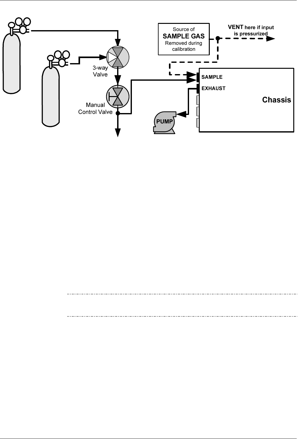
Figure 3-16: Pneumatic Connections, Using Bottled Span Gas
3.3.2.6. SAMPLE GAS SOURCE
Attach a sample inlet line to the SAMPLE inlet port. The SAMPLE input line
should not be more than two (2) meters long.
Maximum pressure of any gas at the SAMPLE inlet should not exceed 1.5 in-
Hg above ambient pressure and ideally should equal ambient atmospheric
pressure.
In applications where the sample gas is received from a pressurized
manifold, a vent must be placed on the sample gas before it enters the
analyzer. Please refer to Figure 3-16.
3.3.2.7. CALIBRATION GAS SOURCES
The source of calibration gas is also attached to the SAMPLE inlet, but only
when a calibration operation is actually being performed.
Note
Zero air and span gas flows should be supplied in excess of the 120 cm
3
/min
demand of the analyzer.
3.3.2.8. INPUT GAS VENTING
The span gas, zero air supply and sample gas (if pressurized) line MUST be
vented (Figure 3-16) for two reasons: in order to ensure that the gases input do
not exceed the m
aximum inlet pressure of the analyzer, and to prevent back
diffusion and pressure effects. These vents should be:
At least 0.2m long;
No more than 2m long and;
Vented outside the shelter or at least into a well-ventilated area and away
from the immediate area surrounding the instrument
07276B DCN6418