Principles of Operation Teledyne API T803 CO2/O2 Analyzer Operation Manual
208
chamber. This dual wavelength method of measuring CO
2
allows the instrument
to compensate for ancillary effects like sensor aging and contamination.
12.3. OPERATION WITHIN THE T803 ANALYZER
Operationally, both the CO
2
and O
2
sensors are transparently integrated into the
core analyzer operation. All functions can be viewed or accessed through the
front panel.
The CO
2
concentration is displayed in the upper right-hand corner, alternating
with O
2
concentration.
Test functions for the slope and offset of CO
2
and of O
2
are viewable from the
front panel along with the analyzer’s other test functions.
Calibration of each
sensor is performed via the front panel CAL. See
Section 9 for more details.
Stability of each
sensor can be viewed via the front panel (see Section 9).
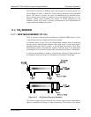
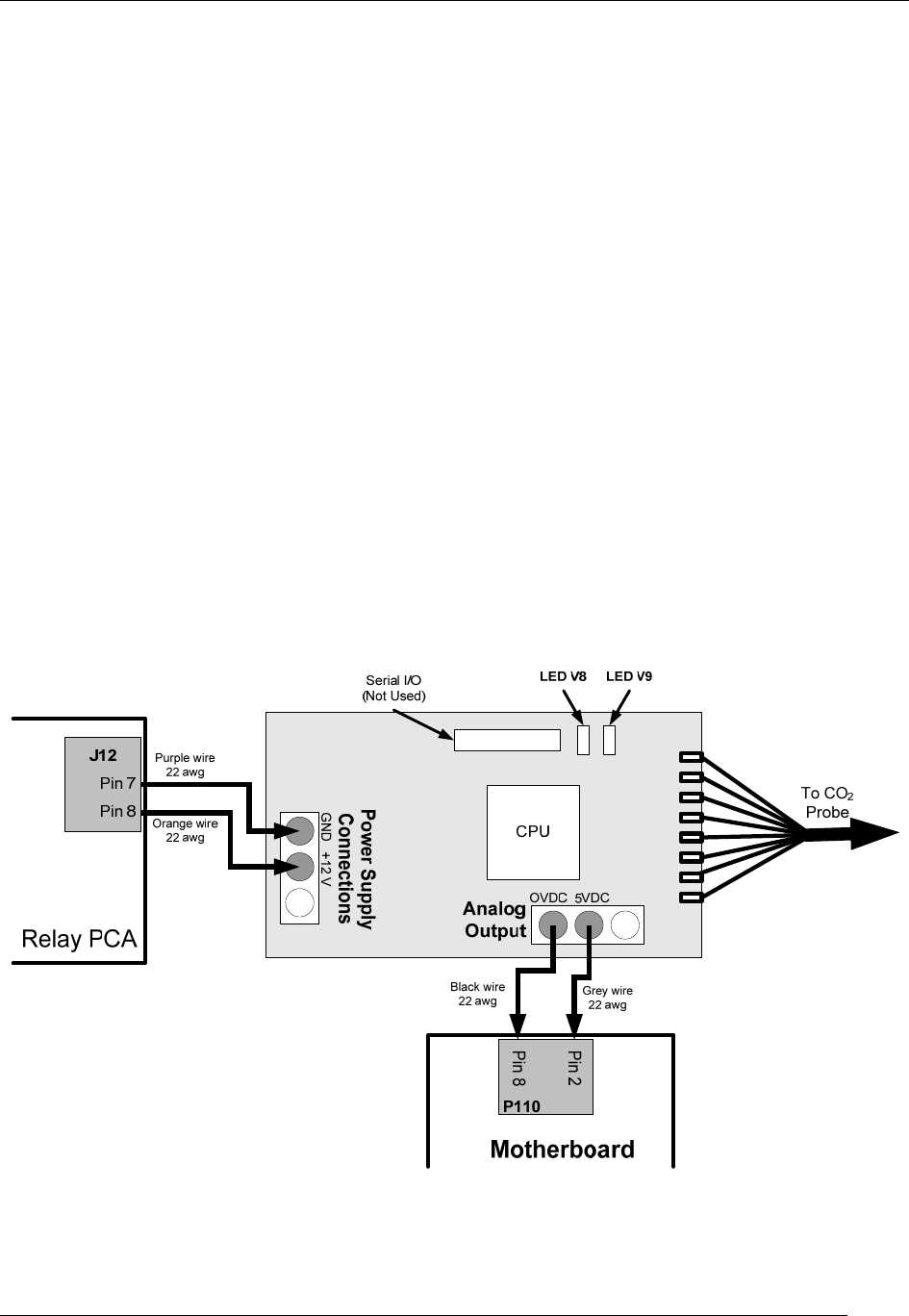
12.3.1.1. ELECTRONIC OPERATION OF THE CO
2
SENSOR
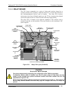
The CO
2
PCA is powered by 12 VDC from the analyzer via the relay card, which
outputs a 0-5 VDC analog signal to the analyzer’s CPU via the motherboard that
corresponds to the concentration of CO
2
measured by the probe.
Figure 12-4. CO
2
Sensor PCA Layout and Electronic Connections
07276B DCN6418


