


Getting Started Teledyne API T803 CO2/O2 Analyzer Operation Manual
34
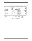
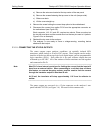
3.3.1.3. ANALOG OUTPUT CONNECTIONS
The T803 is equipped with several analog output channels accessible through the
ANALOG OUT connector on the rear panel of the instrument. The standard
configuration for these outputs is VDC. An optional current loop output is
available for each (Section 3.3.1.4).
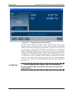
When the instrument is in its default configuration, channel A1 ou
tputs a signal
that is proportional to the CO
2
concentration of the sample gas. If Dual or Auto
range is configured, channels A1 and A2 each output a signal proportional to the
CO
2
concentration of the sample gas. Please refer to Section 5.4.3 for details.
Channel A3 outputs a signal proportional to the O
2
concentration of the sample
gas.
Channel A4 is special. It can be set by the user (see Section 5.10.6) to output any
one of the parame
ters accessible through the <TST TST> buttons of the unit’s
front panel menu.
To access these signals attach a strip chart recorder and/or data-logger to the
appropriate analog output connections on the rear panel of the analyzer.
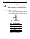
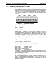
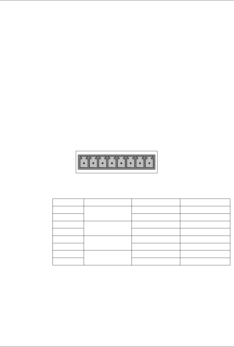
A
NALOG OUT
A1
A
2 A3 A4
+ - + - + - + -
Figure 3-7: Analog Output Connector
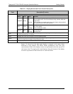
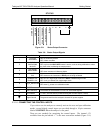
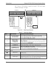
Table 3-5: Analog Output Pin-Outs
PIN ANALOG OUTPUT VOLTAGE SIGNAL CURRENT SIGNAL
1 V Out I Out +
2
A1
Ground I Out -
3 V Out I Out +
4
A2
Ground I Out -
5 V Out I Out +
6
A3
Ground I Out -
7 V Out NA
8
A4
Ground NA
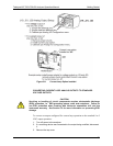
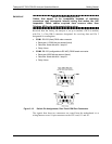
3.3.1.4. CURRENT LOOP ANALOG OUTPUTS (OPTION 41) SETUP
This option adds isolated, voltage-to-current conversion circuitry to the
analyzer’s analog outputs. This option may be ordered separately for any of the
analog outputs; it can be installed at the factory or added later. Call TELEDYNE
API Sales for pricing and availability.
07276B DCN6418