


Troubleshooting and Service Teledyne API T803 CO2/O2 Analyzer Operation Manual
194
11.5.1. TEMPERATURE PROBLEMS
Individual control loops are used to maintain the set point of the temperatures to
both sensors.. If any of these temperatures are out of range or are poorly
controlled, the T803 will perform poorly.
BOX TEMPERATURE
The box temperature sensor is mounted to the motherboard and cannot be
disconnected to check its resistance. Rather check the BOX TEMP signal using
the SIGNAL I/O function under the DIAG Menu (See Section 5.9). This
parame
ter will vary with ambient temperature, but at ~30
o
C (6-7° above room
temperature) the signal should be ~1450 mV.
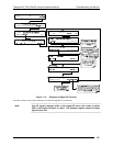
11.6. SUBSYSTEM CHECKOUT
Section 10 discussed a variety of methods for identifying possible sources of
failures or performance problems within the analyzer. In most cases this included
a list of possible causes. This describes how to determine individually determine
if a certain component or subsystem is actually the cause of the problem being
investigated.
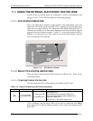
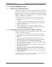
11.6.1. AC MAINS CONFIGURATION
The analyzer is correctly configured for the AC mains voltage in use if:
1. The Sample Pump is running.
2. If incorrect power is suspected, check that the correct voltage and frequency
is present at the line input on the rear panel.
If the unit is set for 230 VAC and is plugged into 115VAC, or 100VAC the
sample pump will not start, and the heaters will not come up to
temperature.
If the unit is set for 115 or 100 VAC and is plugged into a 230 VAC circuit,
the circuit breaker built into the ON/OFF Switch on the Front Panel will
trip to the OFF position immediately after power is switched on.
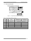
11.6.2. DC POWER SUPPLY
If you have determined that the analyzer’s AC mains power is working, but the
unit is still not operating properly, there may be a problem with one of the
instrument’s switching power supplies. The supplies can have two faults, namely
no DC output, and noisy output.
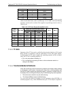
To assist tracing DC Power Supply problems, the wiring used to connect the
various printed circuit assemblies and DC Powered components and the
associated test points on the relay board follow a standard color-coding scheme as
defined in the following table.
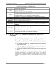
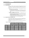
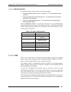
Table 11-5: DC Power Test Point and Wiring Color Codes
NAME TEST POINT# TP AND WIRE COLOR
Dgnd 1 Black
07276B DCN6418