


Teledyne API T803 CO2/O2 Analyzer Operation Manual Troubleshooting and Service
195
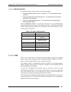
+5V 2 Red
Agnd 3 Green
+15V 4 Blue
-15V 5 Yellow
+12V Ret (ground) 6 Purple
+12V 7 Orange
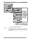
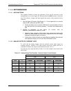
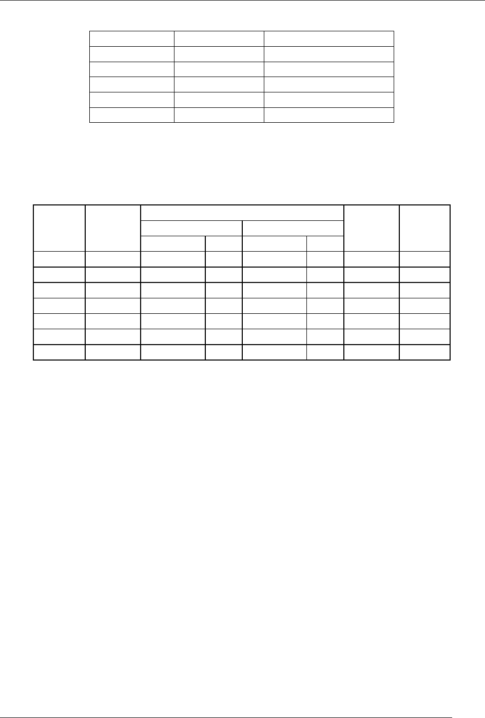
A voltmeter should be used to verify that the DC voltages are correct per the
values in the table below, and an oscilloscope, in AC mode, with band limiting
turned on, can be used to evaluate if the supplies are producing excessive noise (>
100 mV p-p).
Table 11-6: DC Power Supply Acceptable Levels
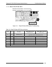
CHECK RELAY BOARD TEST POINTS
FROM TEST POINT TO TEST POINT
POWER
SUPPLY
ASSY
VOLTAGE
NAME # NAME #
MIN V MAX V
PS1 +5 Dgnd 1 +5 2 4.85 5.25
PS1 +15 Agnd 3 +15 4 13.5 16V
PS1 -15 Agnd 3 -15V 5 -13.5V -16V
PS1 Agnd Agnd 3 Dgnd 1 -0.05 0.05
PS1 Chassis Dgnd 1 Chassis N/A -0.05 0.05
PS2 +12 +12V Ret 6 +12V 7 11.75 12.5
PS2 Dgnd +12V Ret 6 Dgnd 1 -0.05 0.05
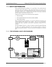
11.6.3. I
2
C BUS
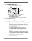
Operation of the I
2
C bus can be verified by observing the behavior of D1 on the
Relay Board in conjunction with the performance of the front panel display.
Assuming that the DC power supplies are operating properly and the wiring is
intact, the I
2
C bus is operating properly if:
D1 on the relay board is flashing, or;
D1 is not flashing but pressing a button on the touchscreen results in a
change to the display.
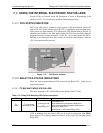
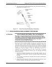
11.6.4. TOUCHSCREEN INTERFACE
Verify the functioning of the touchscreen by observing the display when pressing
a touchscreen control button. Assuming that there are no wiring problems and
that the DC power supplies are operating properly, if pressing a control button on
the display does not change the display, any of the following may be the problem:
The touchscreen controller may be malfunctioning.
The internal USB bus may be malfunctioning.
You can verify this failure by logging on to the instrument using APICOM or a
terminal program to any of the communications ports. If the analyzer responds to
07276B DCN6418