


Principles of Operation Teledyne API T803 CO2/O2 Analyzer Operation Manual
218
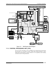
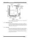
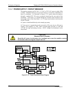
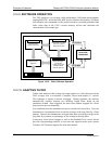
12.6.5. MOTHERBOARD
This printed circuit assembly provides a multitude of functions including, A/D
conversion, digital input/output, PC-104 to I
2
C translation, temperature sensor
signal processing, and serves as a pass-through for the RS-232 and RS-485
signals.
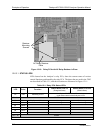
12.6.5.1. A TO D CONVERSION
Analog signals, such as the voltages received from the analyzer’s various sensors,
are converted into digital signals that the CPU can understand and manipulate by
the analog to digital converter (A/D). Under the control of the CPU, this
functional block selects a particular signal input (e.g. BOX TEMP) and then
converts the selected voltage into a digital word.
The A/D consists of a voltage-to-frequency (V-F) converter, a programmable
logic device (PLD), three multiplexers, several amplifiers and some other
associated devices. The V-F converter produces a frequency proportional to its
input voltage. The PLD counts the output of the V-F during a specified time
period, and sends the result of that count, in the form of a binary number, to the
CPU.
The A/D can be configured for several different input modes and ranges but in
the T803 the A/D is used in uni-polar mode with a +5 V full scale. The converter
includes a 1% over and under-range. This allows signals from –0.05 V to +5.05
V to be fully converted.
For calibration purposes, two reference voltages are supplied to the A/D
converter: Reference Ground and +4.096 VDC. During calibration, the device
measures these two voltages, outputs their digital equivalent to the CPU. The
CPU uses these values to compute the converter’s offset and slope and uses these
factors for subsequent conversions.
See Section 5.10.3 for instructions on performing this calibration.
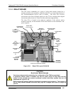
12.6.5.2. SENS
O
R INPUTS
The key analog sensor signals are coupled to the A/D through the master
multiplexer from two connectors on the motherboard. 100K terminating resistors
on each of the inputs prevent cross talk from appearing on the sensor signals.
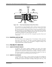
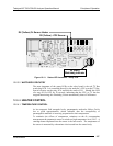
SAMPLE PRESSURE AND FLOW
These are analog signals from two sensors that measure the pressure and flow rate
of the gas stream at the outlet of the sample chamber. This information is used in
two ways. First, the sample pressure is used by the CPU to calculate O
2
Concentration. Second, the pressure and flow rate are monitored as a test
function to assist the user in predicting and troubleshooting failures.
12.6.5.3. THERMISTOR INTERFACE
This circuit provides excitation, termination and signal selection for several
negative-coefficient, thermistor temperature sensors located inside the analyzer;
there is a thermistor for the O
2
sample chamber housing, which reports the
07276B DCN6418