


Principles of Operation Teledyne API T803 CO2/O2 Analyzer Operation Manual
216
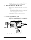
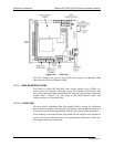
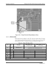
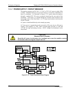
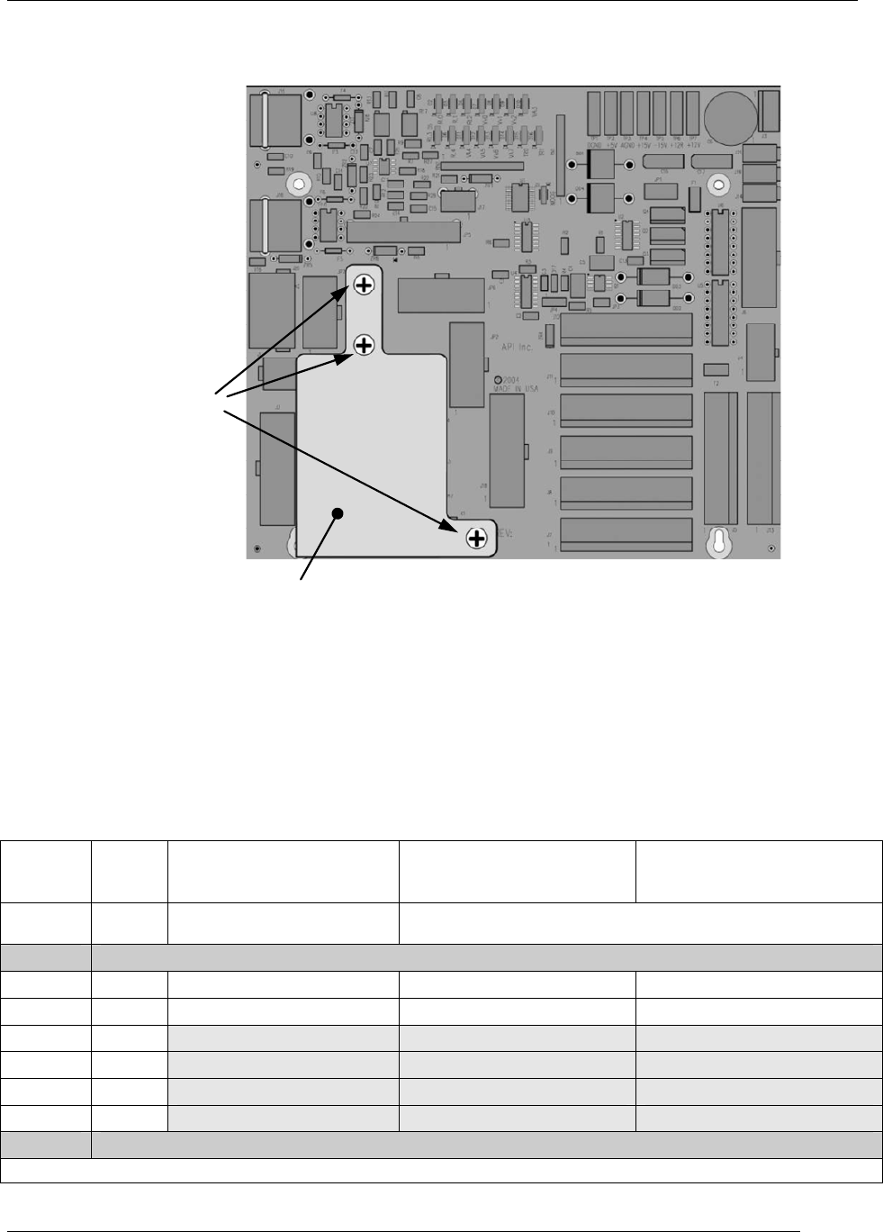
AC Relay Retainer
Plate
Retainer
Mounting
Screws
Figure 12-10: Relay PCA with AC Relay Retainer in Place
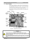
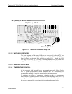
12.6.3.1. STATUS LEDS
LEDs located on the Analyzer’s relay PCA, show the current status of various
control functions performed by the relay PCA The three that are used in the T803
are described in Table 12-1, and their locations are illustrated in Figure 12-11.
Table 12-1: Relay PCA Status LEDs
LED Color Function
Status When LED Lit
(Energized State)
Status When LED Unlit
(Default State)
D1
Red Watchdog Circuit
Cycles ON/OFF every 3 Seconds
under direct control of the analyzer’s CPU.
D2-D4 SPARE
D5
Yellow CO
2
Sensor Cell heater Heating Not Heating
D6
Yellow O
2
Sensor heater Heating Not Heating
D7
2
Green
D8
2
Green
D9
2
Green
D10
2
Green
D11 - 16 SPARE
2
Not Used.
07276B DCN6418