


February 2002 © TOSHIBA TEC 6 - 1 FC-210/310 POWER SUPPLY UNIT
6. POWER SUPPLY UNIT
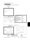
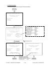
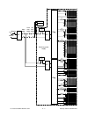
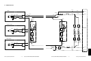
6.1 Output Channel
There are four output channels which are not linked with the door switches, as shown below.
(1) 3.3V(M) — For MPU on the SYS board, the image processing circuit, etc.
3.3VA : Pins 4 and 5, J707
Output to: IMC board, SYS board, AI board (via the IMG board), IMG board
3.3VB : Pin 1, J708
Output to: SCM board
(2) 5.1V(M) — For mechanical control circuits on the LGC board, IMC board, SCM board,etc.
5.1VA : Pins 3, 4 and 5, J706
Output to: LGC board
5.1VB : Pins 6 and 7, J707
Output to: IMC board, SYS board, RLY board (via the IMC board),
AI board (via the IMG board), IMG board
5.1VC : Pins 1, 2, 3 and 4, J710
Output to: built-in printer controller (optional)
5.1VD : Pins 3 and 4, J708
Output to: SCM board
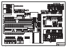
(3) 12V(M) — Mainly for analog circuits and the HDD (e.g. image quality sensor, color registration sensor)
12VA : Pin 10, J706
Output to: LGC board, IMC board (via the LGC board),
image quality sensor (via the LGC board),
registration sensor (via the LGC board)
12VB : Pin 7, J708
Output to: SCM board, SDV board (via the SCM board), HDD
12VC : Pins 9, 10, 11 and 12, J710
Output to: built-in printer controller (optional)
(4) 24V(M) — For RADF, the finisher, fans, etc.
24VH : Pin 1, J706
Output to: LGC board
24VI : Pin 9, J708
Output to: SCM board
24VJ : Pins 1 and 3, J709
Output to: finisher