MJ-1103/1104 © 2008, 2009 TOSHIBA TEC CORPORATION All rights reserved
DISASSEMBLY AND INSTALLATION
4 - 64
4.6 Motor (Finisher section)
[A] Entrance motor (M1)
[B] Buffer tray guide motor (M2)
(1) Take off the Junction box unit.
P.4-13 "[A] Junction box unit"
(2) Take off the FIN board.
P.4-120 "[A] Finisher control PC board
(FIN board)"
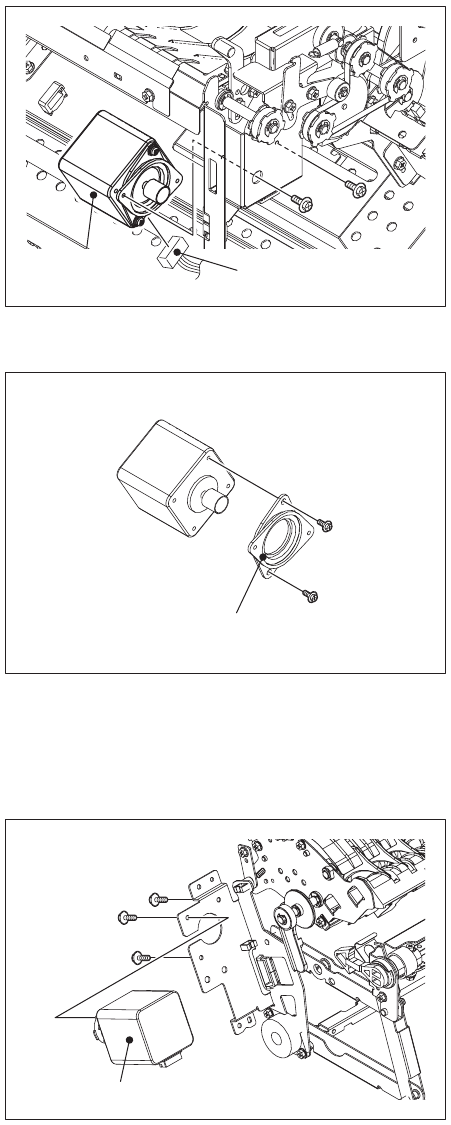
(3) Remove 2 screws. Then disconnect the con-
nector to take off the entrance motor.
Fig. 4-180
(4) Remove 2 screws, and then remove the
motor damper.
Fig. 4-181
(1) Take off the buffer unit-1.
P.4-17 "[C] Buffer unit-1"
(2) Remove 3 screws, and then take off the
buffer tray guide motor.
Fig. 4-182
Connector
Entrance motor
Motor damper
Buffer tray guide motor


