


4
© 2008, 2009 TOSHIBA TEC CORPORATION All rights reserved MJ-1103/1104
DISASSEMBLY AND INSTALLATION
4 - 101
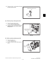
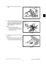
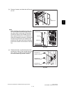
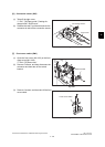
(3) Remove 2 screws, and then take off the sen-
sor rail.
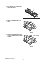
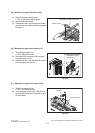
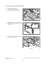
Note:
When installing the movable tray drive unit,
fix it at the position where the gap between
the center mark of the scale on the sensor
rail and the edge of the movable tray posi-
tion-a sensor is from 0 to 1 mm. Be sure to
adjust the installation position by shifting the
movable tray shift frame and measure the
positions at the upper and lower measuring
points on the sensor rail as shown in the fig-
ure.
Fig. 4-284
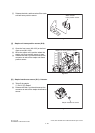
Fig. 4-285
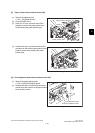
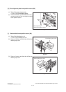
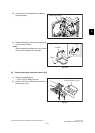
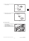
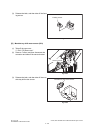
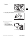
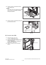
(4) Release the latch, and then disconnect the
connectors to take off the movable tray posi-
tion-a sensor, movable tray position-B sen-
sor and movable tray position-c sensor.
Fig. 4-286
Sensor rail
Sensor rail
Sensor
0mm to 1.0mm
Measure
Movable tray
position-B sensor
Movable tray
position-A sensor
Movable tray
position-C sensor