


4 Replacement Procedures
TECRA S3 Maintenance Manual (960-532) [CONFIDENTIAL] 4-v
Figure 4-25 Removing the USB board ............................................................................ 4-39
Figure 4-26 Removing the internal microphone.............................................................. 4-41
Figure 4-27 Removing the SR board/DC-IN jack........................................................... 4-43
Figure 4-28 Connecting the SR/USB cable..................................................................... 4-44
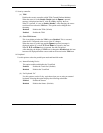
Figure 4-29 Removing the fan......................................................................................... 4-45
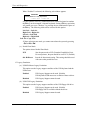
Figure 4-30 Removing the CPU heat sink....................................................................... 4-47
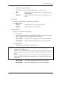
Figure 4-31 Removing the CPU ...................................................................................... 4-48
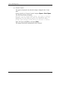
Figure 4-32 Applying silicon grease ............................................................................... 4-49
Figure 4-33 Removing the GPU heat sink....................................................................... 4-50
Figure 4-34 Removing the GFX board............................................................................ 4-51
Figure 4-35 Removing the HDD cable holder................................................................. 4-52
Figure 4-36 Removing the modem jack .......................................................................... 4-53
Figure 4-37 Removing the HDD cable............................................................................ 4-53
Figure 4-38 Removing the PC card slot .......................................................................... 4-54
Figure 4-39 Removing the north bridge IC heat sink...................................................... 4-54
Figure 4-40 Removing the FP board ............................................................................... 4-56
Figure 4-41 Removing the display mask......................................................................... 4-58
Figure 4-42 Removing the FL inverter............................................................................ 4-59
Figure 4-43 Removing the LCD unit (1)......................................................................... 4-60
Figure 4-44 Removing the LCD unit (2)......................................................................... 4-61
Figure 4-45 Removing the LCD bracket ........................................................................ 4-62
Figure 4-46 Peeling off the insulator............................................................................... 4-62
Figure 4-47 Removing the LCD cable holder ................................................................. 4-63
Figure 4-48 Removing the cover latch ............................................................................ 4-65
Figure 4-49 Removing the wireless LAN antenna cable................................................. 4-66
Figure 4-50 Removing the wireless LAN antenna/Bluetooth antenna............................ 4-67
Figure 4-51 separating the display cover and middle frame ........................................... 4-68
Figure 4-52 Removing the hinge (right).......................................................................... 4-69
Figure 4-53 Removing the hinge (left)............................................................................ 4-70
Figure 4-54 Removing the speaker.................................................................................. 4-72
Figure 4-55 Removing the battery slider A..................................................................... 4-73
Figure 4-56 Removing the battery slider B ..................................................................... 4-74