2 Troubleshooting Procedures
2-8 [CONFIDENTIAL] TECRA S3 Maintenance Manual (960-532)
Procedure 2 Error Code Check
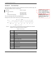
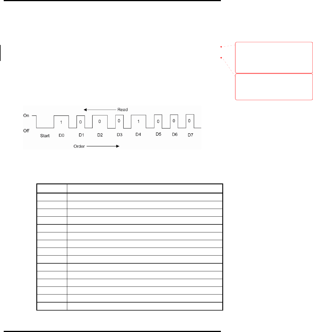
If the power supply microprocessor detects a malfunction, the DC IN icon blinks orange. The
blink pattern indicates an error as shown below.
Start Off for 2 seconds
Error code (8 bit)
“1” On for one second
“0” On for half second
Interval between data bits Off for half second
The error code begins with LSB (Least Significant bit).
Example: Error code 11h (Error codes are given in hexadecimal format.)
Check 1 Convert the DC IN icon blink pattern into the hexadecimal error code and
compare it to the tables below. Then go to Check 2.
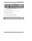
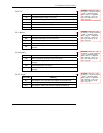
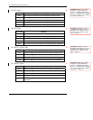
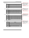
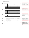
Table 2-3 Error code
Error code Where Error occurs
1*h DC IN (AC Adapter)
2*h 1
st
battery
3*h 2
nd
battery
4*h S3V output
5*h E5V output
6*h E3C output
7*h 1R5-E1V output (CH0)
8*h 1R8-B1V output
9*h PPV output
A*h PTV output (CH0)
B*h 1R5-E1V output (CH1)
C*h PGV output
D*h VG1R8-P1V output
E*h PTV output (CH1)
F*h -
Formatted:
Indent: Left: 17.85 pt,
Hanging: 17.85 pt, Numbered +
Level: 1 + Numbering Style: Bullet +
Start at: 1 + Alignment: Left + Aligned
at: 18 pt + Tab after: 0 pt + Indent at:
36 pt, Tabs: 18 pt, Left
Formatted:
Numbered + Level: 1 +
Numbering Style: Bullet + Start at: 1 +
Alignment: Left + Aligned at: 18 pt +
Tab after: 0 pt + Indent at: 36 pt,
Tabs: 18 pt, Left


