


3 Hardware configuration
92
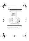
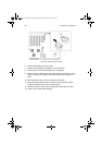
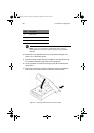
8 Slide the notched end of the new front panel board into the slot in
the front subchassis.
9 Position the board so the snap-top standoff on the front of the
chassis is aligned with the hole in the front panel board and press
the board over the standoff.
10 Insert and tighten the mounting screw to secure the board to the
front subchassis.
11 Reconnect the cables to the front panel board: the front panel
board ribbon cable, the intrusion switch cables, the USB cable, and
the serial port cable.
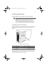
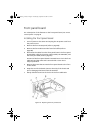
12 Install the foam fan baffle and the fan modules.
13 Install the front access panel.
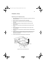
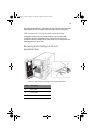
Label Description Label Description
A Front panel board cable D Screw
B USB and serial port cables E Snap-top standoff
C Chassis intrusion cables F Slot in chassis
AA G900 ug - EN.book Page 92 Wednesday, September 25, 2002 5:23 PM