


3 Hardware configuration
72
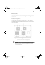
5 Prepare the new PCI board for installation:
a Remove the add-in board from its protective wrapper. Be
careful not to touch the components or gold edge connectors.
Place the add-in board with the component side up on an
antistatic surface.
b Record the serial number of the add-in board in your
equipment log.
For a sample equipment log sheet, refer to page 197.
c Set jumpers or switches according to the manufacturer's
instructions.
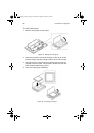
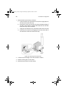
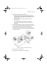
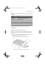
6 On the edge opposite the connectors, grasp the board by both
corners. Orient the board to the vacant hot-plug slot so that the
metal retention bracket is toward the rear of the chassis.
7 Insert the board into the front and rear retention mechanisms.
Carefully push down on the board until it engages and fully seats
in the slot connector.
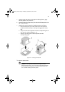
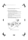
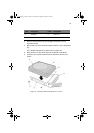
8 Close the front and rear latches.
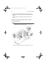
9 Reinstall the rear access panel (refer to page 45).
Figure 36 - Installing a hot-plug PCI add-in board
AA G900 ug - EN.book Page 72 Wednesday, September 25, 2002 5:23 PM