


59
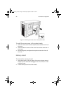
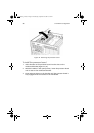
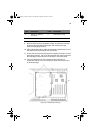
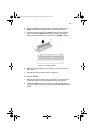
9 Remove the six screws, the plastic overlay, and the two processor
board mounting brackets that attach the mainboard to the
electronics bay (Figure 25, A).
10 Lifting the board slightly, slide the mainboard toward the front of
the chassis until the I/O ports clear the chassis.
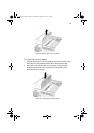
11 At one side of the chassis, the board is inserted into slots in a foam
panel (Figure 25, B). Lift up on the opposite end of the board and
pull the edge of the board out of the slots in the foam panel.
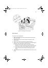
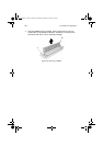
12 Lift the mainboard out of the electronics bay and place it
component-side up on a nonconductive, static-free surface (or in
an antistatic bag).
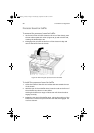
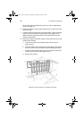
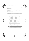
Label Description Label Description
A Tabs (3) on retention
mechanism
C Overlay tab (1 of 2)
B Protective overlay D Overlay screw
Figure 25 - Mainboard mounting
AA G900 ug - EN.book Page 59 Wednesday, September 25, 2002 5:23 PM