


101
Note: Although not necessary, for easier handling, you might
want to remove any drives installed in the drive bay assembly
before proceeding.
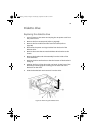
5 If both hot swap drive bays are installed, loosen two of the screws
that secure one side of the other drive bay to the front subchassis.
Loosening the other drive bay allows the drive bay enclosure to
expand slightly, making it easier to remove the drive bay assembly.
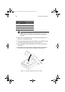
6 Grasp the fan housing on the back of the drive bay assembly and
pull the drive bay assembly out the back of the front subchassis.
7 If you are installing a replacement drive bay, skip to step 5 of the
next section to install that device.
8 Install the foam fan baffle and fan modules (refer to page 88).
9 Install and close the front subchassis (refer to page 49 and
page 50).
10 Install the front access panel (refer to page 46).
Note: If you are not installing a replacement drive bay, install a
metal EMI shield on the opening in the front of the chassis for
proper cooling and EMI shielding.
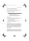
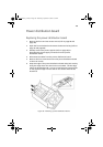
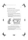
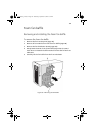
To install a hot-swap drive bay
1 Turn off power to the server and unplug the AC power cords from
the power source.
2 Open and remove the front subchassis (refer to page 47 and 48).
3 Remove the fan modules and the foam fan baffle (refer to
page 88).
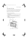
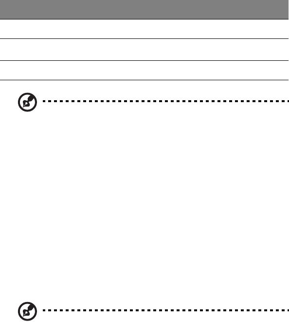
Label Description Label Description
A Screws C Power cables
B
I
2
C cable
DFan cable
C Chassis intrusion cables F Slot in chassis
AA G900 ug - EN.book Page 101 Wednesday, September 25, 2002 5:23 PM