


3 Hardware configuration
102
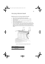
4 If another hot-swap drive bay is already installed, loosen two of
the screws that secure one side of the other drive bay to the front
subchassis. Loosening the other drive bay allows the drive bay
enclosure to expand slightly, making it easier to remove the drive
bay assembly.
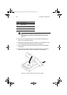
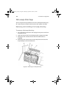
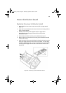
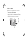
5 From the back of the front subchassis, grasp the rear fan housing
and carefully slide the front end of the drive bay assembly into the
drive bay enclosure.
6 Tighten the four screws (two on each side) that secure the drive
bay assembly to the front subchassis and tighten the screws on the
other drive bay assembly loosened in step 4.
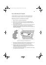
7 Connect the cables to the drive bay assembly backplane.
8 Install the foam fan baffle and fan modules (refer to page 88).
9 Install and close the front subchassis (refer to page 49 and
page 50).
10 Install the front access panel (refer to page 46).
AA G900 ug - EN.book Page 102 Wednesday, September 25, 2002 5:23 PM