


AMD
P R E L I M I N A R Y
112
Am79C930
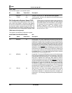
TCR13: Pin Configuration A
This register is the Pin Configuration A register. This
register is used to set the state of various pins as outputs
or as high impedance inputs.
CONFIGURATION REGISTER INDEX: 0Dh
Bit Name Reset Value Description
7 LNKEN 1 Link LED Enable. LNKEN can be used to control the function of the
LNK LED output. The control of the function of the LNK pin is de-
scribed in the
Multi-Function Pin
section.
6 LFPEEN 1 LFPE Enable. LFPEEN is used to determine the function of the
LFPE pin. The control of the function of the LFPE pin is described in
the
Multi-Function Pin
section.
5 HFPEEN 1 HFPE Enable. HFPEEN is used to determine the function of the
HFPE pin. The control of the function of the HFPE pin is described
in the
Multi-Function Pin
section.
4 SDCLKEN 1 SDCLK Enable. SDCLKEN is used to determine the function of the
SDCLK pin. The control of the function of the SDCLK pin is de-
scribed in the
Multi-Function Pin
section.
3 SDS3LEN 1 SDSEL3 Enable. SDS3LEN is used to determine the function of the
SDSEL3 pin. The control of the function of the SDSEL[3] pin is de-
scribed in the
Multi-Function Pin
section.
2 SDS2LEN 1 SDSEL2 Enable. SDS2LEN is used to determine the function of the
SDSEL2 pin. The control of the function of the SDSEL[2] pin is de-
scribed in the
Multi-Function Pin
section.
1 SDS1LEN 1 SDSEL1 Enable. SDS1LEN is used to determine the function of the
SDSEL1 pin. The control of the function of the SDSEL[1] pin is de-
scribed in the
Multi-Function Pin
section.
0 RXPELEN 1 RXPE Enable. RXPELEN is used to determine the function of the
RXPE pin. The control of the function of the RXPE pin is described
in the
Multi-Function Pin
section.
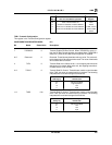
TCR14: Pin Configuration B
This register is the Pin Configuration B register. This
register is used to set the state of the USER[4:0] pins as
outputs or as high impedance inputs.
CONFIGURATION REGISTER INDEX: 0Eh
Bit Name Reset Value Description
7 USER7EN 0 USER7 Enable. USER7EN, the ISA PnP registers 70h and 71h,
and the PCMCIA pin setting are used to determine the function of
the USER7 pin. The USER7 pin can be programmed to function as
either an input or an output.
The control of the function of the USER7/IRQ11 pin is described in
the
Multi-Function Pin
section.
6 LLOCKEN 0 LLOCKE Enable. LLOCKEN and the PCMCIA pin are used to de-
termine the direction of the LLOCKE/SA15 pin. When LLOCKEN is
set to a 1 and the PCMCIA pin is set to 1, then the LLOCKE/SA15
pin is enabled to drive both high and low output values. LLOCKE
output values are determined by the LLOCKE bit of TIR11. When
LLOCKEN is reset to a 0, then the LLOCKE pin is forced to a high-
impedance state. Reads of the LLOCKE bit of TIR11 will yield the