


AMD
P R E L I M I N A R Y
50
Am79C930
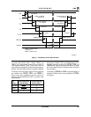
Transceiver-Based TX Power Ramp Control
— The
CTS signal may be used to synchronize operations be-
tween the Am79C930 device and transceivers that wish
to perform their own transmit timing sequence. When
the CTS signal is enabled by setting the CTSEN bit of
TCR7 to a 1, then the CTS input acts as a gating signal
with respect to the start of the Am79C930 transmit op-
erations. An example of the use of the CTS signal would
be when a transceiver is in control of the decision to
transmit. The Am79C930 device must first indicate a de-
sire to transmit by asserting one of the user-definable
output pins to the transceiver and then by setting the
TXS bit of TIR8. These actions place the Am79C930 de-
vice’s transmit state machine in a “wait for CTS” state.
When the transceiver concludes that the medium is free
and a transmission may begin, then it asserts the CTS
signal to the Am79C930 device and the internal
transmit state machine will begin to send data to the
transceiver. For this application, the TXCMD signal
would indicate to the transceiver a desire to transmit,
and the multifunction pin USER1/IRQ12/EXTCTS/
INT188 would provide the return path to the Am79C930
device indicating the transceiver’s decision to proceed
with the transmission.
TX CRC Generation
A CRC may be automatically calculated for each frame
that is transmitted. The CRC is automatically appended
to the end of the frame when an appropriate TIR bit has
been set. The CRC appended to the transmit frame de-
pends upon the setting of the TCRC bits of TIR8. Either
an 8-bit CRC or a 32-bit CRC may be appended. An op-
tion to append no CRC may also be selected. The CRC
that is selected may be changed on a per-frame basis.
When the CRC is appended to an outgoing frame, an in-
terrupt to the 80188 may be generated, depending upon
the setting of the CRCSU unmask bit of TIR6. The
CRCS bit of TIR4 always indicates when the CRC has
been appended to an outgoing frame, regardless of the
state of the CRCSU bit.
The CRC32 polynomial is X32+X26+X23+X22+X16
+X12+X11+X10+X8+X7+X5+X4+X2+X+1; the initial
condition of the CRC32 calculation is FFFF FFFFh; and
the final remainder of the CRC32 operation is
DEBB 20E3h.
The CRC8 polynomial is X8+X5+X+1; the initial condi-
tion of the CRC8 calculation is FFh; and the final ex-
pected remainder of the CRC8 operation is 66h.
TX Status
TIR9 provides bits that indicate the current state of the
Am79C930 device with respect to the transmission of a
frame. For example, the TIR9 bits indicate the number of
bytes currently in the TX FIFO and whether or not the
transmission is active.
Start of Frame Delimiter Detection
Automatic Start of Frame Delimiter (SFD) detection is
built into the Am79C930 device’s TAI subunit. Start of
Frame Delimiter length may be defined as 0 bytes, 1
byte, 2 bytes or 3 bytes. The length of SFD is set with the
SD bits of TCR0. The pattern of the SFD is programma-
ble. The SFD registers TCR8, TCR9, and TCR10 are
programmed by the user with the SFD pattern to be
matched. Register status bits with associated interrupt
capability exist for both Antenna Lock and Start of
Frame Delimiter detected. The various register status
and interrupt unmask bits are located in TIR4, TIR5,
TIR7, TIR9, and TIR26. The FDET output pin signals the
start of frame boundary to external logic and operates
during both RX and TX. Start of Frame Detection is al-
ways calculated based upon network ordering of bits
and is therefore independent of the setting of the WNS
bit (Big vs Little Endian bit ordering control) of TCR3.
The Start of Frame Delimiter search may be performed
by external logic, and the result passed into the
Am79C930 device through the USER6/IRQ5/EXTSDF/
EXTA2DST pin when the ENXSDF bit of TCR28 has
been set to 1. See the
Multi-Function Pin
section for
more detail.
RX Data Parallelization
Once the RX Preamble and Start Of Frame Delimiter
have been located, subsequent bits in the serial RX data
stream are converted to parallel byte format and moved
into the RX FIFO. As the RX FIFO fills with data, the TAI
will request RX data byte removal by asserting the
DRQ0 input of the embedded 80188 core. The RXFC
bits of TIR17 contain the current byte count of the
RX FIFO.
RX FIFO
TAI contains individual FIFOs for RX and TX operations.
The RX FIFO indicates a non-empty state by signaling a
request for data on the DRQ0 input of the 80188 embed-
ded core. The DRQ0 output of the TAI subunit is active if
the RX FIFO condition is met, regardless of the state of
the RXS bit of TIR16. RX FIFO DMA activity
is prevented by disabling the DMA0 controller in
the 80188.
The RX FIFO holds a maximum of 15 bytes of data. The
number of bytes of data residing in the RX FIFO is indi-
cated in TIR17. TAI automatically removes the Pream-
ble and Start of Frame Delimiter from the incoming
frame. Any PHY header that has been passed from the
transceiver to the Am79C930 device will be preserved in
the FIFO, provided that the PHY header is located after
the Preamble and SFD fields.
RX CRC Checking
CRCs are automatically checked on arriving frames.
Registers in the TAI indicate where CRC8 and CRC32