AMD
P R E L I M I N A R Y
120
Am79C930
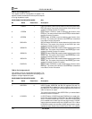
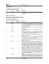
TCR26: Reserved
This register is the TAI reserved location register.
CONFIGURATION REGISTER INDEX: 1Ah
Bit Name Reset Value Description
7–0 Reserved – Reserved. Must be written as a 0. Reads of this bit produce
undefined data.
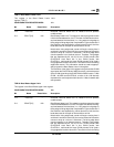
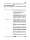
TCR27: TIP LED Scramble
This register is the Network Interface Polarity register.
This register is used to set the polarity of some of the
transceiver interface output pins.
CONFIGURATION REGISTER INDEX: 1Bh
Bit Name Reset Value Description
7 DISRNR 0 Disable RUNERR. When DISRNR is set to a 1, then the RUNERR
bit of TCR11 will always be held at a 0 value. When DISRNR is set
to a 0, then the RUNERR bit of TCR11 will function as described in
the TCR11 bit description.
6 Reserved – Reserved. Must be written as a 0. Reads of these bits produce
undefined data.
5 Reserved 0 Reserved. Must be written as a 0. Reads of these bits produce
undefined data.
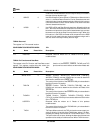
4 LNKDR 0 LNK pin drive. When set to a 0, the drive of the LNK pin will be open
drain. When set to a 1, the drive of the LNK pin will be totem pole,
i.e., both high and low output values will be driven.
Complete control of the function of the LNK pin is described in the
Multi-Function Pin
section.
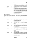
3 ACTDR 0 ACT pin drive. When set to a 0, the drive of the ACT pin will be open
drain. When set to a 1, the drive of the ACT pin will be totem pole,
i.e., both high and low output values will be driven.
Complete control of the function of the ACT pin is described in the
Multi-Function Pin
section.
2 FDETPOL 0 FDET Polarity. When this bit is set to a 0, then the polarity of the
FDET output will be low assert, such that when the SFD pattern has
been recognized in the incoming receive data stream or the outgo-
ing transmit data stream, the FDET pin will be driven to a LOW logic
level. When this bit is set to a 1, then the polarity of the FDET output
will be high assert, such that when the SFD pattern has been recog-
nized in the incoming receive data stream or the outgoing transmit
data stream, the FDET pin will be driven to a HIGH logic level.
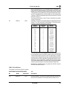
1 TXPEPOL 0 TXPE Polarity. When this bit is set to a 0, then the polarity of the
TXPE output will be low assert, such that when the TGAP1 counter
expires, the TXPE pin will be driven to a LOW logic level. When this
bit is set to a 1, then the polarity of the TXPE output will be high as-
sert, such that when the TGAP1 counter expires, the TXPE pin will
be driven to a HIGH logic level.
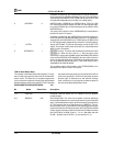
0 TXMODPOL 0 TXMOD Polarity. When this bit is set to a 0, then the polarity of the
TXMOD output will be low assert, such that when the TGAP2
counter expires, the TXMOD pin will be driven to a LOW logic level.
When this bit is set to a 1, then the polarity of the TXMOD output will


